Disruptive fluorescence microscopy
CHRISTOPHER SHUMATE
Microscopes are the most common laboratory instrument in the world—a lab is more likely to have a microscope than any other instrument. As such, microscopy is a field in which innovation is continually producing new advances.
Some of the most dramatic advances in the last decade have affected one of the most common modes of light microscopy. The inverted, epifluorescence, wide-field microscope has been disrupted by progress involving almost every component of its construction. As with mobile phones, the design and performance of current inverted microscopes vastly exceed that of a decade ago, resulting in a new form factor and use scenarios in which function can drive design.
At its most basic, a microscope is an image sensor (one’s eye or a camera), a magnifying lens, a sample holder—and something to look at. Early designs arranged these components in a tube, and as the architecture evolved, a chassis emerged to provide a base, a sample stage, oculars, and controlled illumination. In early iterations, the components were typically adapted to the chassis design. Thus, rather than redesign the chassis to work better with cameras, cameras were created to fit the standard configuration—despite the fact that this demanded a more complex camera design. This traditional microscope chassis design is preserved across the big four microscope vendors and all of their clones (see image at top of this page). This article will discuss the main components of a fluorescence microscope and technological disruption currently affecting each one. It will also demonstrate the impact that they have together on the future of microscopy design.
Illumination
Whereas transmitted light can be supplied by a simple incandescent bulb, fluorescence excitation needs high intensities at specific excitation wavelengths. A variety of arc lamps have been developed to provide enough intensity at the visible wavelengths used for most applications.1 It is interesting to note that early fluorescent dyes were designed to excite at the wavelengths most prominent in the arc lamp’s spectra or available as laser lines. We continue to live with those early-favored wavelengths.
The advent of LEDs and their use in consumer and telecommunications markets pushed the technology to a point where the right wavelengths at sufficient intensity became available. LEDs supply a long list of advantages over arc lamps:
- LEDs require no warm-up or cool-down period
- They can be switched on and off instantly, without the need for a shutter
- LEDs have lifetimes of 10,000 to 50,000 hours compared to hundreds of hours for most arc lamps
- There is no decay in intensity over time
- LEDs cost less than arc lamps
- Intensity can be varied continuously with pulse width modulation
- Power requirements are much lower
- LEDs are narrowband emitters—they do not emit in the low ultraviolet (UV) or the infrared (IR)
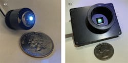
- LEDs illuminate areas that measure a few millimeters across compared to a few centimeters (see Fig. 1)
- Spent LEDs are not considered hazardous waste
Filters
Traditionally, filters have been necessary to select an excitation wavelength and reject the unwanted broad emission of the arc lamp, removing harmful UV and IR wavelengths from the excitation. With the relatively monochromatic LED, excitation filters are used only to slightly narrow its spectra: a dichroic filter is used to reflect the excitation to the sample, allowing longer wavelength emission to pass to the eye or an imaging sensor. These filters need to reject many orders of magnitude of scattered off-excitation wavelengths to image only the emission. A rule of thumb is that scattered light is 1000X the intensity of fluorescence emission.
Modern infinity optics, although more complicated than its finite conjugate counterpart, allowed the introduction of optical components such as filters into the optical path. Filters are most often physically moved into and out of the optics path. Often, three filter wheels work in concert to select the excitation, the dichroic, and the emission range. Changing the optics path inevitably changes the image registration and results in different image shifts, known as pixel shift, for each fluorescent channel.
Dan Pinkel was the first to use multiband-pass filters (see Fig. 2).2 A multiband dichroic allows multiple distinct excitations to be reflected to the sample while transmitting each channel’s respective emission. A matching multiband-pass emission filter further rejects unwanted light from getting to the sensor. This configuration allows the elimination of filter wheels and presents a solid-state, compact filter solution without pixel shift. The limitation is the inability to substitute custom filters in a multiposition wheel, but multiband filter sets for common, well-separated dyes are commercially available.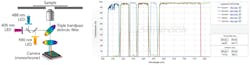
Cameras
The first fluorescence images were captured with long exposures through a single-lens reflex film camera mounted to the chassis through a port with mirrors and lenses, diverting the image from the oculars to the camera. Long exposures require minimum movement or vibration during the exposure. For this reason, most traditional microscopes are placed on large and heavy pneumatic vibration tables.
As astronomy developed the CCD camera for imaging the faint light of distant stars, it became a natural tool for the faint emission of fluorescence microscopy. These cameras are generally expensive and required sophisticated Peltier cooling and electron multiplier electronics.3
Originally, CMOS sensors were of much lower performance, but with the advent of consumer digital cameras and smartphones, the gap has narrowed to the point where Sony, the leader in CCDs for the last 30 years, discontinued production in 2017 and will end shipments in 2020. Now, CMOS sensors have become the dominant sensors in video, smartphone, and DSLR applications due to their low cost and fast readout speed.
Scientific CMOS (sCMOS) denotes the higher performance versions currently used in microscopy. They have impressive quantum efficiency, dynamic range, and dark noise specifications, and are global-shuttered with comparable performance to CCD sensors. It is estimated that CMOS will gradually supplant CCD in even higher-performance applications. Without electron-multiplying devices (emCCDs) or Peltier cooling, CMOS cameras are 2–10X smaller than their CCD counterparts. Weight, size, and environmental resistance allow them to be located in novel microscopy configurations.
The chassis
For most of the history of microscopy, the human eye has been unmatched for image sensitivity. Thus, microscope design has traditionally emphasized oculars, and even in the age of digital imaging, this feature persists in case a digital camera is not installed in the system. This design requires the image to be redirected from the stage to a relatively ergonomic position for viewing. The problem is that more lenses and mirrors in the optics path equates to less signal. A good rule of thumb is that as much as 4% of light can be lost when transitioning from one refractive index material to another. So as light travels through a lens, up to 8% of its intensity is lost. A traditional design might lose over 60% of the photons before reaching the imaging sensor. It should also be noted that more lenses require more alignment to preserve the image delivered by the objective.
Lower photonic efficiency also places demands on background. Signal-to-noise is the name of the game, and great signal is worthless if background is high. To help, darkrooms were built with rotating light-tight doors.
The persistence of oculars can be explained by the fact that they are familiar—therefore, users feel comfortable using them to evaluate images. But as camera and display resolution have improved, a new generation of microscopists have been getting comfortable experiencing their images from 4K monitors through a heads-up display rather than spending hours bent over oculars.
As mentioned previously, higher magnification and sensitivity required a vibration-free environment not provided by the chassis design, and thus vibration isolation tables—with their great mass and pneumatic suspension—became a requirement.
One benefit of the traditional, large-form-factor chassis design is that it enables expansion by way of accessories that interface through ports offered specifically for these upgrades. As new technologies have become available, some of these accessories, including filter wheels, advanced cameras, lasers, spinning disks, and micromirror arrays, have become more expensive than the base platform. Meanwhile, the more common and mundane uses of the instrument become encumbered by the addition of esoteric accessories.
Smaller, cheaper, more powerful
As technology evolves, the products it enables tend to get smaller, less expensive, and more powerful. Microscopy is not immune to this trend, and the components discussed above are heralding a new era of microscope design based on a chassis that minimizes optical path length, the number of elements in that path, and the movement of anything in the path. The disruption paves the way for new companies to enter the market without the legacy of decades-old product line design.
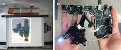
Thanks to advances in illumination, filter technology, and CMOS cameras, an entire microscope can be created that will fit into the palm of a hand. The compact size allows vibration resistance to be built in, so that vibration tables are no longer required. These advances yield dramatic (>2X) increases in sensitivity, decreases in power requirements (5 VDC), and environmental resistance. The increased sensitivity eliminates the need for a darkroom, and the simple design allows workers without technology expertise to easily use the instrument. Reduced size and power requirements means that more cameras can be placed in parallel—and even multiple microscopes to be positioned in tight spaces (see Fig. 3).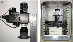
Environmental resistance allows in situ microscopy to be performed in tissue culture incubators, gloveboxes, hypoxia and anaerobic chambers, and even in refrigerators. Monitoring live cell growth and behavior is one of the most powerful uses of modern microscopy in the biomedical field.
REFERENCES
1. See http://bit.ly/BOWref1.
2. See http://bit.ly/BOWref2.
3. See http://bit.ly/BOWref3.
Christopher Shumate, Ph.D., is CEO of Etaluma, Carlsbad, CA; e-mail: [email protected]; https://etaluma.com.