Digital aberrometry enables high-resolution eye measurements
IGOR LYUBOSHENKO
As more therapies become available, doctors increasingly wish to identify diseases as early as possible and monitor their initial stages in order to address them appropriately. In the case of eye maladies such as age-related macular degeneration (AMD), they need to watch the retina so they can time the treatment properly.
Achieving this goal requires imaging the retina at the highest possible resolution. Because diffraction imposed by the iris’s diameter determines maximum image resolution, getting the best result with iris diameters greater than 3 mm necessitates a highly capable aberrometer. An aberrometer, which passes light through the eye and then measures that light as it exits the eye, is the tool an ophthalmologist uses to measure wavefront—the change in shape of the front of the light waves as they exit the cornea. A very capable aberrometer can produce highly resolved 3D images of both the wavefront and the intensity of the light coming out of the eye–with superior dynamic range and in real time. Ophthalmic aberrometry relies on wavefront sensing technologies to enable not only early disease diagnosis and monitoring, but also treatment such as corrective lens prescription or LASIK surgery to improve visual acuity.
Most aberrometers are based on Shack-Hartmann wavefront sensors, which transform the light coming out of the eye into a set of spots (“data points”) on the digital camera. The spots are created when microlenses focus the light onto a camera placed in the lenses’ focal plane. The local slope of the wavefront is proportional to the deviation of a spot from its pre-calibrated position. The standard 400 µm resolution provides 241 data points over a pupil 7 mm in diameter, or 123 measurement points over a 5 mm pupil. Newer systems boast 177 µm resolution, which translates to 1257 points for a 7 mm diameter pupil, or 641 measurement points for a 5 mm diameter pupil.
But the resolution of even the newer sensors is limiting, especially for detection of higher-order aberrations. To measure a wavefront in one pixel, several square pixels are required to detect a spot created by the corresponding microlens. Typically, about 100 pixels provide one measurement of displacement of the spot with respect to its pre-calibrated position–which yields one measurement of a local slope of the wavefront. Thus, a high-resolution image of the retina is not directly available, because the beam reflected from the retina is transformed through the microlens, and the displacements of the resulting set of spots yield the local wavefront gradients. Typically, one spot occupies an area of 10 × 10 pixels on the digital camera, meaning the ability to obtain a high-resolution image of the retina is sacrificed for the purpose of measuring the wavefront.
Current wavefront analyzers provide only low-resolution wavefront data and, in the best case, low-resolution intensity distributions. In the process of transforming light intensity into a series of spots, the original high-resolution data are lost and can only be captured by an independent camera. Therefore, a comprehensive ophthalmic system requires both a digital camera and a wavefront sensor as separate instruments.
Hardware elements such as microlenses and diffractive elements limit the resolution and dynamic range of aberrometers. They also depend to a large degree on the skills of a technician for operations such as pupil location and centering of the device—and thus for their results. No wonder more advanced technology emphasizes the use of software for processing digital images of the retina.
Less hardware, more resolution
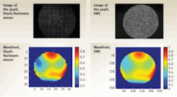
A digital wavefront camera (DWC) is an “all-in-one” instrument that combines a retinal imager and a digital aberrometer–with resolution limited only by the size of one CCD pixel (600 × 600 points for a 6 mm pupil). It is able to measure both wavefront and intensity in high resolution; the greater resolution replaces the spot of the conventional systems with a pixel on the CCD camera. The result is more data points and higher dynamic ranges–which are important for imaging “difficult” eyes (for instance those affected by keratoconus, a degenerative disorder which causes the cornea to become more conical than rounded in shape) (see Fig. 1.).
The video imaging of a DWC allows easier observation of the measured beam–because the full-resolution image enables far more convenient alignment than does the Shack-Hartmann system’s array of spots. The full resolution of the camera allows direct visualization of the intensity image and evaluation of image uniformity. The system enables immediate detection of vignetting (reduction of an image’s brightness or saturation at the periphery), which is less easily diagnosed with Shack-Hartmann sensors because of their limited lateral resolution.
A DWC is capable of measuring wavefronts from -16 to +12diopters (D)—that is, very convex to very concave. Diopter measurement indicates curvature radius of a spherical part of the wavefront; the higher D is, the smaller the radius of curvature, and the steeper the wavefront—and therefore the more challenging it is for a sensor to reconstruct the wavefront. The instrument can perform up to 8 µm root mean square (RMS) measurement of higher-order aberrations—whereas the limit for Shack-Hartmann is 1.6 µm. This provides a more accurate representation of the wavefront—which is particularly useful for examination of eyes affected by scars, keratoconus, or injury, for example—and allows an increase in the image rate, thus increasing both the quantity of eyes imaged and the quality of resulting prescriptions. DWC software performs automatic pupil location, auto-centering and auto-focusing, therefore the aberrometer is technician-independent and more forgiving with respect to human factors.
DWCs can simultaneously measure the wavefront and the pupil image in high resolution (with resolution determined by the number of pixels in the digital camera). The word “digital” refers to the minimal use of hardware components and the intensive use of specialized software algorithms to achieve the best wavefront sensing performance.
DWCs rely upon measurements of the energy redistribution in 3D space: they simultaneously measure both the variation of the wave’s intensity in the optical axis direction and the redistribution of the wave’s intensity in the transverse direction. The 3D measurement of intensity in real time enables the high-resolution measurement of the wavefront—without use of hardware diffracting elements or microlenses–at the cost of increased computational effort.
The path of the beam through space is determined by projecting beams corresponding to different planes transverse to the optic axis onto a digital camera, de-multiplexing the images, and applying complex fast mathematical differential equation solvers to obtain the beam’s wavefront. To measure aberrations in a human eye, a DWC projects a collimated beam of 880 nm infrared light onto the retina, which reflects about 1/1000th of the light. The DWC records this in several positions along the optical axis, and the software computes the high-resolution wavefront (see Fig. 2).
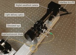
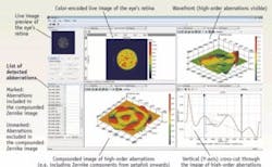
A typical compact aberrometry setup based on DWC is suitable for measuring human eyes in situations where reflectivity is very low and the illumination power density is limited to be well below the maximum permissible exposure (see Fig. 3). Thanks to wavefront analysis, the DWC can typically distinguish between the higher- and lower-order aberrations (see Fig. 4).
How DWC measures up
Testing the accuracy of a DWC in the spherical range of -7D to +6D for a 6 mm pupil begins with measuring defocus in the output of a simulated eye. Then, that measurement is compared with calibrated graduations on the simulated eye to yield a determination of accuracy between -6D and +6D. Similarly, estimating the dynamic range of defocus (or sphere) measurable by DWC for a pupil of approximately 6 mm involves measuring defocus in the output of the simulated eye moved to produce a spherical wavefront in the camera plane. The resulting defocus measurement is then compared to its theoretical value to evaluate accuracy over the range of input values. Deviation from this curve from a given value (linked to accuracy) limits the useful dynamic range of the measurement, which for DWC is from -16D to +12D.
To test the accuracy of DWCs with respect to data from a standard interferometer, we compared values of Zernike coefficients of aberrations from DWC to those of a standard HeNe laser (by Research Electro Optics; Boulder, CO) operating at 633 nm. For the experiments, we used a “model eye” camera (the Skia/Retinoscope Trainer from Heine Optotechnik GmbH; Herrsching, Germany) with a set of ocular lenses able to reproduce typical eye aberrations. The interferometric and DWC readings showed agreement to within the experimental error of the measurements–that is, by less than 3%. Independent measurements of the same phase plates with their manufacturer’s interferometer and with DWC yielded the same results, to within the measurement uncertainty.
Today’s DWCs typically feature sensitivity of l/100 over the entire dynamic range of several hundreds of wavelengths. Resolution can reach approximately 360,000 measurement points per aperture diameter of 6 mm. With no use of hardware elements, DWCs enable measurements in a broad illumination frequency spectrum, including infrared frequency band. They also perform well in low-light conditions thanks to power delivery requirements set forth by the maximum permissible exposure regulations. And, they provide measurement frequency of 15 Hz or higher. DWCs can measure tilts, divergence, and convergence of the wavefronts.
DWCs open up new opportunities for characterization of human visual acuity. When used in aberrometers, the high resolution in wavefront reconstruction coupled with simultaneous measurement of high-resolution light intensity promises higher quality vision correction prescriptions, and better outcomes of cornea laser ablation procedures. Being able to handle higher-order aberrations is potentially important for elderly patients—with AMD and other disorders. Overall, the approach facilitates treatment of a wider range of patients, and ultimately improves treatment planning and outcomes.
Igor Lyuboshenko is CEO of PhaseView, Palaiseau, France; www.phaseview.com, [email protected].


