Free-space links address the last-mile problem
Isaac I. Kim and Maha Achour
Wireless optical-mesh networks coupled with microwave communications are helping to overcome the bottleneck in metro/access communications.It's called "the last-mile" problem: studies show that fewer than 5% of all buildings in the United States have a direct connection to a high-speed (above 2.5 Gbit/s) fiberoptic backbone, yet more than 75% of businesses are within one mile of the fiber backbone. Most of these businesses are running some high-speed data network within their building, such as fast Ethernet (100 Mbit/s), or Gigabit Ethernet (1.0 Gbit/s). Yet their Internet access is provided by the significantly lower-bandwidth technologies available though the existing infrastructure such as copper wire (T1 at 1.5 Mbit/s), cable modem (5 Mbit/s shared), and digital subscriber line (DSL; 6 Mbit/s one way). The last-mile problem is the connection of the high bandwidth from the fiberoptic backbone to all of the businesses with high-bandwidth networks.
Free-space optical (FSO) communications systems can provide a line-of-sight, wireless, high-bandwidth communications link between remote sites. The FSo communications are similar to fiberoptic communications in that data is transmitted by modulated laser light. Instead of containing the pulses of light within a glass fiber, they are transmitted in a narrow beam through the atmosphere. Because free-space and fiber use similar optical transmitters and detectors, they can achieve comparable high-bandwidth capabilities (up to gigabit speeds). Wavelength-division multiplexing (WDM) technologies will work in free-space, further increasing the bandwidth potential of wireless optical links.
Along with significantly increased data rates, FSO has many advantages over other wireless technologies such as microwave or RF-spread-spectrum. These include license-free operation, and increased security due to the laser's narrow beam, which makes detection, interception, and jamming nearly impossible. In addition, FSO terminals are mobile and quickly deployable, making them ideal for disaster recovery and temporary installations.
The advantages of FSO over fiberoptic cabling are primarily economic. Free-space communications offer an attractive alternative to the prohibitive cost of trenching the streets to lay fiber, the logistical complexity of obtaining right-of-way permits, and the recurrent costs associated with leasing fiber lines. There is a disadvantage: FSO communications are subject to atmospheric effects such as attenuation and scintillation, which can reduce link availability and may introduce burst errors.
Other than cost, the most significant difference between free-space and fiberoptic laser transmission is the unpredictability of laser power attenuation in the atmosphere. Fiberoptic cables attenuate at a constant, predictable rate, while atmospheric attenuation is quite variable and difficult to predict since it is weather-dependent. Current multimode fiberoptic cables attenuate at 2 to 3 dB/km, and single-mode fibers attenuate at 0.5 to 0.2 dB/km. Atmospheric attenuation loss can vary from 0.2 dB/km in exceptionally clear weather to 350 dB/km in a very dense fog. The large attenuation values in heavy fog can reduce the uptime or availability of FSO systems.
The effects of precipitation on FSO are far less severe than the effects of fog. Even in the heaviest rain (cloudbursts of 100 mm/hr), the maximum attenuation is 20 dB/km. This is because the fog-droplet radius (5 to 15 µm) is on the order of a laser wavelength, whereas rain-droplet sizes range from 200 to 2000 µm.
The atmosphere also causes rapid fluctuations in power (called scintillation) at the detector. Technologies to reduce the effects of scintillation include the use of multiple transmit apertures and larger receive apertures (see Fig. 1). Compared to fiber systems, FSO systems require more link margin because of unpredictable attenuation and scintillation.
Link limitations
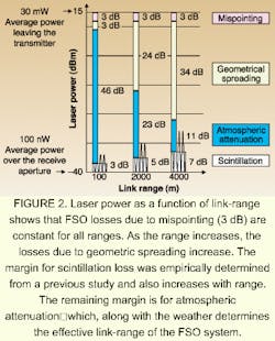
Typical FSO-link power budgets vary as a function of link range (see Fig. 2). The geometric spreading loss rapidly increases with range because the transmitting laser-beam divergence is set to be greater than the diffraction limit (typically 3 to 10 mrad). This extra mispointing allowance keeps the FSO transceivers aligned, even in the presence of excessive wind or a small amount of building sway. Allowing some margin for scintillation fade loss, the remaining link margin for atmospheric attenuation determines the effective link-range of the FSO system.
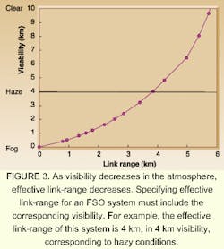
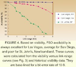
The effective link-range is also a function of the weather, decreasing with limited visibility. Sample losses are 0.5 dB/km for clear weather, 3 dB/km in haze, and 30 dB/km for fog (see Fig. 3). A more useful indicator of FSO system performance can be derived by combining the link-range as a function of visibility with regional, historical visibility data. This results in an estimate of the availability of an FSO system as a function of link-range (see Fig. 4).1
If FSO systems are to be used in telecommunication applications, there are requirements for very high availability that must be met. For example, the link margin for atmospheric attenuation for the budget in Figure 2 is 44 dB at 125 m. In order to meet that telecom availability, FSO links should be less than 125 m (to overcome the worst weather scenario of heavy 350-dB/km fog).
In realistic urban environments, however, it is difficult to have all FSO links between buildings that are less than 125 m apart. Free-space links greater than 125 m should be backed up by lower-data-rate microwave links. Having a radio and laser in tandem works particularly well, since microwave transmission is affected more by rain (because the carrier wavelength is closer to the size of a rain drop) and laser transmission is affected more by fog. Recent studies show that conditions of simultaneous heavy rain and thick fog, which would cut out both the laser and microwave transmissions, are extremely rare. These statistical weather studies indicate that the telecom benchmark of 99.999% availability is achievable at shorter ranges with a primary FSO system backed up by a microwave.
Originally, FSO found a niche market with enterprise networks. A company needing a high-speed connection between two of its buildings, each running a Fast Ethernet or asynchronous transfer-mode (ATM) network, would select FSO for its connection after looking at the high cost and availability of fiber versus the low bandwidth of microwave. Telecom availability was traded off for lower cost and higher bandwidth. As it turned out, because of error correction and retransmission built into these network protocols, the very small amount of downtime due to weather was usually unnoticeable to the users. Today, the much larger metro/access market is accessible by pairing FSO with a radio backup (to provide the 99.999% availability) with intelligent classification network switches. The FSO system will have its largest impact in solving the metro/access last-mile problem.
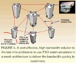
The current fiberoptic backbone runs to central offices in most of the large population centers in the United States. There has been much work done to upgrade the fiberoptic backbone by extending its reach and increasing its bandwidth. The high bandwidth capability of the 2.5-Gbit/s to 10-Gbit/s and beyond fiberoptic backbone has been achieved by improvements in switching and optical components and with the implementation of technologies such as WDM. Most of the recent effort of digging up the ground and laying down new fiber has been directed toward extending the fiberoptic backbone to new central offices and not laying fiber directly to the customer (see Fig. 5).
There are many ways to define the topology of the last-mile networks, such as the level of flexibility, scalability, and redundancy each provides to the network. Ring topologies consist of multiple links and nodes deployed in closed loops. Although ring networks are not easily scalable, they provide a high level of survivability at the expense of transmitting the same traffic along different directions. Point-to-multipoint topology is deployed by defining cells, which are constructed with a powerful and expensive base-station that links remote users in a shared-environment scenario.
A meshy question
Mesh topologies provide flexible solutions for last-mile access because they not only increase network redundancy but also do not require excess bandwidth to duplicate the traffic. Currently, most mesh topologies are based on ATM protocol. However, last-mile networks are quickly migrating to native Ethernet protocol because it seamlessly integrates with end-user networks without consuming high traffic overhead. With emerging multiple-protocol label-switching, Ethernet will not only guarantee quality of service for real-time and critical applications, but also will simplify traffic-engineering control.
The lower-speed microwave backup allows all the nodes within the mesh network to be accessible at all times, even when the nodes are completely immersed in dense fog. By using innovative techniques, lower-speed backup links are introduced to the mesh topology while still supporting the vital quality of service switching and routing standard techniques.
The best way to overcome preconceived notions of the weather limitations of FSO is to educate potential users on the actual effects of weather. It is critical to never oversell the capabilities of FSO or an FSO/radio system. As long as FSO is used within its capabilities, it could become the preferred high-bandwidth wireless technology for telecom carriers and the effective and economic solution to the last-mile bandwidth bottleneck. In addition, FSO will continue its traditional role in Gigabit Enterprise applications, and in complementing fiber in ring closures as well as backing up fiber for redundancy.
REFERENCE
- I. Kim et al., Opt. Eng. 37, 3143 (1998).
ISAAC I. KIM is director of research, and MAHA ACHOUR is director of advanced technology at Optical Access Inc., 10343 Roselle St., San Diego, CA 92121; e-mail: [email protected].


