FIBERS FOR ILLUMINATION: Fiber-delivered halogen serves as workhorse for machine vision
LED illumination offers life-cycle advantages but heat dissipation and efficiency barriers still block LED use in practical fiber applications.
Ivan Maksymyk
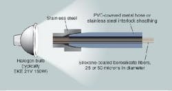
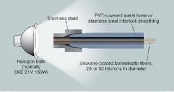
Illuminators that incorporate halogen sources coupled to fiber bundles deliver a surprisingly intense, uniform, and stable illumination. Despite their simplicity, such illuminators are the lighting workhorses in many machine-vision and visual-microscopy applications (see Fig. 1). If a fiber bundle (typically 1/4 to 1/2 in. in diameter) is held at the focal point of a standard 150-W, ANSI code EKE, halogen bulb, the power density (illuminance) in the bundle is about 1M lux-at least one order of magnitude greater than direct sunlight at the surface of Earth. This value establishes the highest possible illuminance available at any point downstream, and is often sufficient for even the most light-hungry applications, notably paper inspection and postal sorting.
Fiberoptic delivery of light has a number of useful features. Principally, it permits the source to be spatially separated from the target, which spares the target area from unnecessary heat and allows for bulb replacement without the dismantling of the optical head of a system. Moreover, unwanted content of the radiation, such as IR or UV, can be removed by placing a filter between the source and the bundle face.
To compensate for any lack of uniformity in the source’s radiation pattern, the fibers in a fiber bundle undergo a randomization process during bundle fabrication. Fiber randomization ensures that a sample of light from each part of the source is transmitted to each part of the illumination field. A high degree of uniformity (±1%) can be readily achieved in this way, and increased randomization can improve uniformity to arbitrarily high levels.
Linescan applications
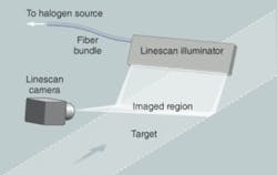
For the reasons given above-separation of source and target, high intensity, and the possibility of uniformity through randomization-fiber-delivered halogen is a suitable and relatively inexpensive illumination option in many specialized machine-vision and visual-microscopy applications, such as lighting for high-throughput linescan, which poses challenging requirements for intensity, stability, and uniformity (see Fig. 2).
Few machine-vision applications are as demanding on lighting as linescan. In the multistep fabrication of high-quality products, in which yield is all-important, 100% linescan inspection is becoming increasingly frequent. A case in point, high-end linescan-camera sales are growing annually at more than 20%, while the overall growth rate of machine-vision solutions is considered to be less than 10% for North America. Major linescan applications include semiconductor surface inspection, web inspection (of foil, paper, nonwovens and plastic films), flat-panel-display inspection, parcel processing and mail sorting, and lumber sizing and profiling.
At the heart of a linescan system is a digital CCD or CMOS camera that incorporates an array of several thousand pixels in a single row. Such cameras are capable of line acquisition rates on the order of several tens of kilohertz. The linescan technique allows for the detection and the classification of defects. It also provides the digital images for lumber sizing and profiling, and for optical character recognition in postal sorting.
Manufacturers implement linescan because it is the method that allows the highest possible throughput for inspections involving the two-dimensional imaging of a continuously moving target. To keep the same spatial resolution, any increase in target speed must be accompanied by a proportionate increase in line acquisition rate. And the faster the line acquisition rate, the more intense must be the lighting. In other words, lighting can never be bright enough in high-throughput linescan. The highest intensities are required in paper inspection and mail sorting. In paper inspection, the speed of the target can be as high as several tens of meters per second. The highest linescan illuminance requirements are of the order of 500 klux.
High brightness is required even more in linescan applications that cannot tolerate noise. In such cases, the camera gain must be kept low. The low gain must be compensated by increased illuminance.
Not only is the average optical power level important, but so is the stability (or constancy) of the optical power. The stability requirement is particularly demanding in film thickness or material density linescans, which are sometimes performed through a measurement of optical attenuation. Ideally, in such inspections, the optical power should vary no more than one part in a thousand. The current generation of linescan cameras have as many as 14 bits of resolution on each pixel (about 16,000 digital numbers). This degree of intensity resolution is obviously of reduced usefulness if the illumination has poor temporal stability.
To achieve the required stability, optical feedback loops based on photodiodes and analog feedback must be implemented. Halogen-based fiberoptic illuminators capable of yielding long-term stability of ±0.1% are now being commercialized. Several technical difficulties have been addressed to deliver these illuminators to the market, including the photo-aging of photodiodes and the temperature-dependence of photodiode response, both of which can contribute significantly to system instability.
Free-space LED illuminators
Fiber-delivered halogen can deliver the brightness, stability, and uniformity required in demanding linescan applications. The use of bulb technologies nonetheless presents certain disadvantages. Halogen bulbs fail catastrophically after only roughly 2000 hours. Their emission spectra evolve over time, and color temperature is a strong function of the power level at which the lamps are operated.
Light-emitting diodes (LEDs) are an attractive emerging alternative. Unlike bulbs, LEDs do not fail catastrophically, but simply become dimmer over time. LED lifetime-defined as being the time when output drops to half of the original value-is several tens of thousands of hours (about five years).
Particularly important, the recent offerings of LED chips represent a milestone in the history of semiconductor lighting. Chips released over the past several months are so efficient that they permit the creation of LED-based illuminators able to compete successfully with halogen. This is a first. Using the thermally efficient chip-on-board method, it is now possible to produce free-space linescan illuminators that project illuminances well over 200 kilolux, with the same degree of uniformity as halogen fiberoptic systems (see Fig. 3).
It is important to appreciate the similarity between fiberoptics and free-space LED illumination. Because the surface of an LED chip is usually a Lambertian emitter, it emits a radiation pattern concentrated in a 120° cone. On the other hand, the face of an optical fiber in a fiberoptic illuminator typically emits in an 83° cone. Therefore, a row of closely spaced LED chips is quite similar to a row of closely spaced fiber faces. Both illuminators essentially consist of a randomized set of point sources, with the individual constituents sufficiently small and sufficiently close to one another to mimic a continuous, uniform strip of emitter.
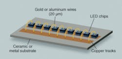
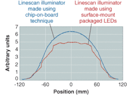
In order for LEDs to replicate the illumination field of a fiberoptic line, the chips must be deposited on a substrate using a technique called chip-on-board. This method allows for the almost back-to-back deposition of the chips. It is tempting to produce linescan illuminators incorporating a row of high-efficiency surface-mount LED packages. However, the large footprint of these packages (often roughly 1 cm) sometimes precludes their use in machine vision. With center-to-center source spacing as large as 1 cm, it is not possible to project uniform fields of illumination at short working distances. In comparing two similar LED systems, one in chip-on-board configuration and the other in surface-mount, at a working distance of 40 mm-typical of space-constrained machine-vision applications-the surface-mount solution displayed undesirable structure in the field of illumination. The chip-on-board solution however gave a field of illumination that was indistinguishable from that generated by fiberoptic illumination (see Fig. 4).
Fiber-delivered LED illumination
So far, we have considered free-space LED line lights, and compared them to fiber-delivered halogen line lights. Is it possible to power a fiber bundle using an LED source, and compete successfully with halogen?
To understand the difficulty of using LEDs in fiber-delivered illumination, consider a long row of 100 LED chips, and consider also a 10 × 10 matrix of the same LED chips. Suppose that both the linear array and the square array have the same center-to-center chip spacing. The crucial point is that although both arrays have the same number of chips, it is clearly much easier to remove heat from the linear array. That is why the first success of high-power LED illumination has been in free-space line lights, and why it is quite difficult to make LED fiberoptic illuminators. Such devices require the operation of matrices of densely packed LEDS, which are inherently thermally challenging.
As LED encapsulant materials with lower absorption are developed, and as LED chips become more efficient, serious LED-based fiberoptic illuminators will begin to appear. These devices, if they are to compete with halogen, will at first have to be water-cooled, but in many applications the potential inconvenience of water-cooling will be more than compensated by the remarkable advantages (reliability and long lifetimes) that semiconductor sources offer.❏
REFERENCES
1. 2004 Annual Report, DALSA Corporation
2. W. Conard Holton, Inside Imaging, Laser Focus World 40(7) 61 (July 2004).
IVAN MAKSYMYK is involved in product management and business development at StockerYale, 32 Hampshire Rd., Salem, NH 03079; e-mail: [email protected]; www.StockerYale.com.
