Rugged fiberoptic links target challenging RF applications
A packaging technique for optical modules that incorporates off-the-shelf components placed and maintained in position with submicron accuracy for free-space optical transmission is providing high-frequency RF (radio-frequency) fiberoptic links for remote antennas in demanding environments.
Numerous RF communication and signaling applications require or benefit from the placement of remote antennas at telecommunication-scale distances that can range from tens of meters to a couple of kilometers away from central signal processing equipment. While copper cabling has been used for low-frequency signals over short-distance links, copper tends to run out of bandwidth with increasing frequencies and distances. Fiberoptic, cabling on the other hand (first suggested for RF transmission about 15 years ago), offers several advantages over copper, such as low loss over relatively long path lengths; flexible, small-diameter, and low-weight cable; immunity to electrical interference; and lack of electrical conductivity.
Analog presents challenges
Because the RF signals are analog, as opposed to the digital optical signals usually transmitted over fiber, a primary challenge in actually implementing this capability has been the development of modulating laser transmitters with sufficient linearity at applications with increasingly high RF frequencies. Direct intensity modulation of laser bias current using RF signal power has been used for relatively short distance telecom applications and for signal frequencies up to a few gigahertz.
The use of an electro-absorption modulator monolithically integrated on the same chip with the laser has enabled further increases up toward 12 GHz for applications such as cable TV. The best frequency performance has been achieved using a modulator separate from the laser, however, particularly for satellite communication backhaul applications in KU-band frequencies from 12 to 18 GHz (the KU satellite transmission band enables the use of small satellite dishes about 2 ft in diameter).
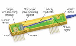
Several potential KU-band applications, particularly in areas of military and civilian aviation and shipping, also place stringent packaging applications-in terms of weight, ruggedness, and size-on the modulator-amplifier pair. For instance, a U.S. Navy contract was recently awarded to Phasebridge (Pasadena, CA) through EDO (Morgan Hill, CA) to upgrade antenna systems in Maritime Patrol aircraft. The Phasebridge RF-optical link uses a lithium niobate modulator chip coupled through free space to a 1550‑nm continuous-wave distributed-feedback laser-diode chip, by way of two-lens collimated-beam coupling (see figure).
The necessary submicron component-positioning accuracy is achieved using a low-cost electrical-resistance spot-welding technique originally developed for RF fiberoptic links but also used in optical modules for other applications, such as compact external-cavity mode-locked lasers and fiberoptic gyros (See Laser Focus World, July 2005, p. S3).
“Packaging an 18‑GHz modulator is nontrivial because all of the electrical train must be precisely impedance-matched to avoid multiple reflections,” according to Steffen Koehler, vice president of marketing at Phasebridge. “The lengths and types of the RF wire bonds are critical, for example, as is the metallurgy of each bond, pad, and electrode. The layout of the package is extremely critical.”
An additional challenge comes in maintaining submicron tolerances in a link package collocated with an antenna on the wingtip of a tactical aircraft or on the antenna mast of a battleship, for instance. In such applications, the laser-modulator pair must fit together in a compact package and function through high levels of shock and vibration, and over a much wider temperature range for military applications (-54°C to +85°C) than is required for telecom applications (-5°C to +70°C), Koehler said. The latter requires balancing different coefficients of expansion over numerous materials.
“Over such a broad range, every component in the optical train (such as the laser, modulator, and lenses) and mounting scheme has its own thermal coefficient of expansion, which means they all want to move in different directions as the temperature changes,” he said. “The challenge is to keep all of the elements aligned with submicron precision despite changing temperature, shock, and vibration.”
About the Author
Hassaun A. Jones-Bey
Senior Editor and Freelance Writer
Hassaun A. Jones-Bey was a senior editor and then freelance writer for Laser Focus World.
