Parallel fiber lays it out for DWDM systems
Olof Svenonius and Paul Duran
Parallel-fiber interconnects allow network service providers to deploy scalable systems with higher capacity.
The rapid growth of global Internet traffic, resulting in a doubling of bandwidth requirements every six to nine months, is driving the rapid deployment of scalable communications equipment. To this end, new systems with terabit capacity are being designed that include multiple interconnected chassisthe largest systems include up to 1000 chassis. Network equipment manufacturers are finding that parallel fiber is the best and in many cases the only solution to interconnect these chassis, since the performance of single-fiber and copper interconnects is limited in terms of bandwidth, density, and distance.
Fiberoptic network service providers are moving quickly to add bandwidth by shifting to dense wavelength-division multiplexing (DWDM). The data handling requirements that result for the optical crossconnects (OXCs) are driving the need for space-saving interconnects that handle increased capacity. The OXC can no longer realistically use traditional single-fiber connections due to space restrictions of getting the required amounts of data to and from the crosspoint switch matrix. Using parallel-fiber links enables increased bandwidth with the additional advantages of reduced space requirements. This results in fewer chassis, lower cost, and lower power consumption.
In addition, use of a parallel-fiber structure allows networking companies to develop systems that are scalable, offering service providers the flexibility to increase capacity by easily expanding to multiple racks or higher frequencies needed for next-generation systems.
Parallel links
A parallel fiber contains 4, 8, or 12 fibers laying side-by-side in a ribbonized parallel cable configuration. A parallel-fiber link contains the fiber ribbon cable, as well as the transmitter and receiver modules, and a single MT-type connector (such as MPO/MTP from USConec or MPX from Tyco Electronics) on each end that connects all of the fibers within the ribbon cable.
Parallel-fiber links can interconnect between different chassis in large-capacity switches, routers, crossconnects, and data-transport equipment. Some recently developed parallel-fiber transmitter and receiver modules can handle 12 channels in a single 16-mm wide component. This translates to the highest board data-rate density of any interconnect scheme.
These modules can be used in an OXC structure that switches wavelength channels at a crosspoint in a DWDM system (see Fig. 1). Since the DWDM optical fiber carries multiple wavelength channels, large amounts of data must be transferred to and from the crosspoint switch matrix. Because of their high-density nature, OXC applications are well suited for using parallel fiber for the connections between the input/output (I/O) chassis and the crosspoint switch matrix.
In a typical OXC, the wavelength data streams enter the crosspoint switch matrix from a line card (see Fig. 2, left). In the DWDM crosspoint switch matrix (center), the signals are directed to the appropriate output (right). Parallel-fiber transmitter and receiver modules convert the electrical signals to optical (E/O) and vice versa (O/E).
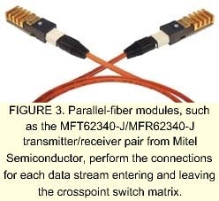
Using a single fiber for each wavelength connection would be prohibitive due to cost, space, and power consumption. In contrast, parallel-fiber modules can provide significant space, cost, and power-saving implications for these applications (see Fig. 3).
Bandwidth Density
The increasing data-rate capacity of network equipment, and the space constraints of existing central office environments, is placing more importance on the amount of bandwidth handled per inch of connector face panel. Parallel-fiber modules provide significant improvements over single-fiber solutions. The 12 x 2.5-Gbit/s parallel-fiber module from Mitel Semiconductor, for instance, is 16-mm wide, which is only slightly wider than a Small Form Factor (SFF) single-channel module, thus enabling more than four times the bandwidth per inch of face panel, as compared with a 2.5-Gbit/s SFF transceiver (see Fig. 4).
A typical DWDM OXC-switch application can be implemented using multiple S2090 68 x 69 crosspoint switches and S2092 retimers from Applied Micro Circuits Corp. (AMCC; San Diego, CA) using a highly dense three-stage nonblocking switch system that can be connected via parallel-fiber links (see Fig. 2).
If individual transmitters were used in this application, there would be a significant routing problem in such a small area. A typical crosspoint switch card measures 12 in. and, by using parallel-fiber modules, it can handle up to 180 2.5-Gbit/s data streams per board edge using single-sided boards, or approximately 38 Gbit/in. In contrast, a typical single-channel solution would allow only 43 2.5 Gbit/s data streams, or 7 to 9 Gbit/s/in. (see table on p. 163). In an OXC, board traffic is essentially limited by the density of the interconnects to and from the crosspoint switch matrix board. The high board density of the parallel-fiber link offers an attractive solution.
Power
In any densely constructed system, power dissipation is a concern and finding efficient means to remove power from an area is an ongoing design challenge. One approach is to select components that offer better power dissipation than traditional solutions. Parallel-fiber modules, for example, reduce the power used by the system as compared to single-channel transceivers.
The use of a parallel solution typically results in a 50% reduction in power requirements as compared to single-fiber solutions, which significantly impacts cost, capacity, and data capacity per board (see Fig. 5).
Distance
Copper solutions are limited by distance, which is becoming increasingly significant as more racks of network equipment are added. For instance, at 2.5 Gbit/s, a multimode fiber can link network equipment that spans 300 m, while a copper solution can deliver across only a few meters.
Current distance requirements in fiberoptic systems include 20- to 36-in. spans within a single chassis, up to 30-m distances within a single room, up to 300 m within a central office and, in some cases, up to 2 km for a large central office. The vast majority of links in a central office are shorter than 300 m, and interconnects using parallel-fiber modules are well suited for these applications.
Cost
As with any communications system, besides performance and space savings, cost is one of the major market drivers. Here is another area where using a parallel architecture can provide an advantage. The cost per gigabit for a single-channel transceiver ranges from about $23 to $92, while the cost for a 12-channel parallel solution is about $7 per gigabit.
Advances in packaging technology also are helping to reduce costs. For instance, about three years ago, Mitel Semiconductor established its Smart OSA packaging technology, which automatically self-aligns the vertical-cavity surface-emitting laser to the fiber connector interface, saving time and expense. In traditional packaging technologies, the lasers require manual or automatic alignment to each fiber for maximum coupling, which add time and cost.
OLOF SVENONIUS is a product line manager at Mitel Semiconductor (Kanata, Ont., Canada), and PAUL DURAN is product marketing manager at Applied Metro Circuits Corp. (San Diego, CA); e-mail: [email protected] and [email protected].