Tunable lasers enhance fiber sensors
Tunable lasers developed for the telecommunications industry will ultimately lead to increased network intelligence, functionality, and efficiency. But the photonics manufacturing expertise, product innovation, and business maturity that resulted from the explosive growth of the telecom industry—especially advances made in tunable-laser technology will also benefit nontelecom markets, including industrial sensing, biotechnology, and semiconductor manufacturing.
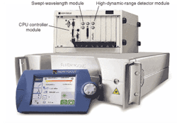
Tunable lasers developed for telecom, for example, are being successfully used in the sensing market as the optical source in fiber-Bragg-grating (FBG) sensing systems (see Fig. 1). These lasers will lead to faster, more accurate, and more sensitive systems. The use of telecom tunable lasers in FBG systems is natural, because the wavelengths of FBG devices are typically centered in the 1550-nm region.
Because their temperature and strain states directly affect their reflectivity spectrum, FBGs can also be used for a wide variety of sensing applications. As the fiberoptic analog to conventional electronic sensors, they can be used as strain-gauge sensors by structural engineers, yet FBGs can also provide measurements that have not been previously possible. Applications include detecting changes in materials like stress in buildings, bridges, and airplane bodies, depth measurements in streams, rivers, and reservoirs for flood control, and temperature and pressure measurements in deep oil wells.
One fiber, many sensors
The advantages of using fiber Bragg gratings for remote sensing include improved accuracy, sensitivity, and immunity to electromagnetic interference, radio-frequency interference, and radiation. The devices are compact, lightweight, and rugged and can thus be embedded or laminated into structures or materials, creating "smart" materials; they can also operate in harsh environments where conventional sensors could not (for example, under water or at high temperatures). The ability to be multiplexed and the inherent low fiber loss at 1550 nm allow many of these sensors to be used on a single optical fiber at arbitrary spacing. Using WDM technology, including tunable lasers, each sensor can be interrogated independently, providing a distributed measurement over large structures. The sensors are also easy to install and use; because the gratings are multiplexed on a single fiber, many sensors can be accessed with a single connection to the optical source and detector (with conventional electronic strain-gauge sensors, each sensor must have its own lead wires attached and routed). Finally, the sensors are potentially low in cost as a result of high-volume telecommunications manufacturing.
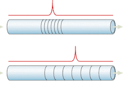
The physical principle behind the FBG sensor is the strain, stress, and temperature sensitivity of a wavelength filter (the fiber Bragg grating) written in the optical fiber itself. The FBG wavelength filter consists of a series of perturbations in the index of refraction along the length of the optical fiber (see Fig. 2). This index grating reflects a narrow spectrum that is directly proportional to the period of the index modulation and the effective index of refraction. The wavelength at which the reflectivity peaks is called the Bragg wavelength. Temperature and strain directly affects the period of the index modulation as well as the effective index of refraction, thus any change in temperature and strain directly affects the Bragg wavelength. In the 1550-nm (C-band) window, a change in mechanical or thermal strain on the FBG results in a wavelength/strain sensitivity of 1.2 pm/µstrain and a wavelength/temperature sensitivity of 10 pm/°C. The gauge lengths of typical fiber Bragg gratings are up to 5 mm, although longer gauge lengths of up to 100 cm are being developed for civil structure applications.
Fiber Bragg gratings are fabricated by writing an index grating directly into a doped optical fiber. Two intense ultraviolet beams are angled to form an interference pattern with the desired periodicity and are incident upon the side of bare fiber after the external coatings have been stripped. The intense bright and dark bands cause local changes in the index of refraction through migration of the dopants in the fiber. After the grating is written, the fiber is recoated with polyamide.
When writing many sensors on a single optical fiber, careful consideration of the specifications of each FBG must be made. For instance, the allowable strain range for any given FBG sensor depends on the available optical bandwidth. If there are multiple FBG sensors multiplexed together on a single fiber, each sensor must be allotted its own wavelength segment so that their signals do not overlap. Thus, as the FBGs experience strain, they shift in wavelength within their allotted optical bandwidth range. This is similar to WDM, in which each channel is given a specific wavelength. In general, there should be a 0.5-nm wavelength buffer between sensor channels. The maximum excursion of each sensor will depend upon the application.
FBG sensor light sources
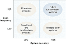
To measure wavelength shifts that are a direct result of changes in temperature or tension, FBG sensor systems must consist of an optical source that continuously interrogates the reflection spectrum, and a detection module that records the shifts in the peak reflectivity vs. wavelength. The overall system sensitivity depends directly upon the wavelength accuracy of the source and detection module—the better their wavelength accuracy, the higher the sensitivity. However, higher wavelength accuracy often results in slower update rates, or scan frequencies, thus leaving the sensors monitored less frequently. The system scan frequency is a combination of the speed of the optical source, the bandwidth of the detectors, and the data acquisition rate, as well as the rate at which the analysis of the wavelength shift can be performed. For applications such as maintenance checks of an airplane's structural integrity, slower—but more accurate—systems are desirable. In other applications where in situ monitoring is required, high update rates are essential.
The simplest FBG sensor system uses a broadband light source, such as an amplified-spontaneous-emission (ASE) white-light source, with a tunable filter and a detector. Because detectors are wavelength insensitive, a tunable wavelength filter is required to scan the wavelength range of the FBG sensors (typically 40 nm) to determine the sensors' Bragg wavelength. The main advantage of these systems is that they are lower in cost, but because the output power from the ASE white-light source is low, only a limited number of in-line gratings can be measured and with a limited dynamic range. Moreover, an external wavelength filter that is needed limits the accuracy and scan frequency of these systems. One system that uses fiber Fabry-Perot tunable filters, for example, can measure up to 31 FBG sensors, offers better than 1-pm resolution, ±10-pm accuracy, 12-dB dynamic range, and has a scan frequency of 50 Hz.
Replacing the broadband white-light source with a laser provides higher output powers and thus an increase in both the number of FBG sensors that can be monitored and the available dynamic range. In addition, a laser emits only a narrow spectrum of optical radiation, thus eliminating the need for a tunable filter. One configuration that uses a laser is based on a fast swept-wavelength fiber laser. Because of the higher output powers, these systems can monitor a total of 256 FBG sensors on four fibers. Moreover, these fiber-laser-based systems offer better than 1-pm resolution, an improved accuracy of ±5 pm, and a larger dynamic range of 30 dB. With the removal of the tunable filter and the extremely fast scan rates of the fiber laser, the update rate of these systems is 100 Hz.
Narrow-linewidth, low-noise, swept-wavelength external-cavity diode lasers (ECDLs) provide even higher output powers than fiber lasers, further increasing both the number of available sensors and the dynamic range (see Fig. 3). Just as for the fiber laser, these low-noise swept-wavelength lasers were also originally designed for high-performance in situ test and measurement of passive telecom network components on the manufacturing floor. The ECDLs sweep at 100 nm/s, offer more than 1 dBm of output power, and have low amplified stimulated emission—more than 70 dB lower than the carrier. These characteristics improve the accuracy and dynamic range of FBG sensor systems. Moreover, by incorporating a swept-wavelength meter, system accuracy can be improved to better than 0.5 pm.
Fiber sensors at work
Fiber-Bragg-grating sensing systems that use low-noise swept-wavelength lasers are being investigated for monitoring stress in airplanes, efficient oil-well recovery, and flood control. In the latter example, FBGs are placed in rivers upstream of populated areas. Early-warning systems constantly monitor the changes in pressure. Large changes enable these systems to provide enough warning to safely evacuate affected areas.
Currently, ECDL-based FBG systems have lower scan frequencies than those based on fiber lasers because the overall system scan frequency depends upon the laser scan speed, the swept-wavelength meter acquisition and analysis, and the FBG acquisition and analysis. Nonetheless, future developments in ECDL technology will soon provide ultrafast tuning rates of up to 10,000 nm/s, enabling both high-speed and highly accurate sensing systems. And, with the cost-effective manufacturing of FBG and tunable ECDL systems that resulted from the telecom era, FBG systems using tunable ECDLs will be cost-competitive with existing remote-sensing systems.
About the Author
Mark Wippich
Mark Wippich is a board member of Vescent Photonics (Golden, CO) and a corporate development advisor.
Kathy Li Dessau
Kathy Li Dessau is product manager at Newport New Focus (Santa Clara, CA).