Interest grows in components based on holey fibers
Microstructured or "holey" fibers have generated a wave of excitement because they promise properties that cannot be achieved in conventional optical fibers. The light-guiding properties of conventional fibers are limited by the properties of the materials from which they are made. Internal microstructures add another degree of freedom in controlling the light-guiding in fibers and, as in semiconductor electronics, this opens new possibilities in designing devices.
One attraction of holey fibers is their potential to guide light through air, avoiding the absorption, nonlinear properties, and material dispersion of solids. Microstructures can do much more, however. Fibers can be made highly nonlinear for such applications as wavelength conversion and Raman amplification. Waveguide dispersion can be adjusted over a broader range than is possible in solid fibers. Birefringence also can be controlled. Researchers are still exploring the potential of the field, and it remains to be seen how many potential applications will prove practical.
A new technology
Holey fibers evolved from the concept of the photonic bandgap, a material that blocks propagation of light with certain wavelengths, like a semiconductor bandgap blocks electrons with energies between the valence and conduction bands. The photonic bandgap is a microstructure made of alternating layers of two materials with different refractive indexes, which acts like a thin-film interference coating to selectively reflect or reject certain wavelengths. The wavelengths selected depend on the thickness and refractive indexes of the layers.
Holey fibers contain two materials, a transparent solid—usually glass—and air contained in holes that run the length of the fiber. The fibers are made by stacking tubes and solid rods together, fusing them, and then drawing the fused bundle into a fiber. The size and spacing of holes defines the microstructure.
The terminology can be confusing. The broad area is called either "holey" or microstructured fibers. Developers distinguish between two distinct types, depending on whether light is guided through a solid core or a hollow zone. The light-guiding properties of both types of fibers depend on the size and spacing of holes in the microstructure as well as the refractive index of the solid matrix.
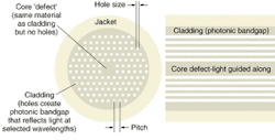
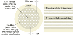
Photonic-crystal fibers have a solid core surrounded by a cladding layer containing holes running the length of the fiber (see Fig. 1). The solid core is sometimes considered a defect, a missing hole in a region filled with holes. The cladding is a photonic-bandgap material, but its average refractive index is lower than that of the solid core, so a photonic-crystal fiber functions like a conventional solid fiber, with a high-index core surrounded by a lower-index cladding. However, the effective index of the holey cladding varies with wavelength and depends on the size and spacing of the holes.
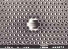
Photonic-bandgap fibers have a hollow core surrounded by a photonic-bandgap cladding, which guides light through the air-filled core (see Fig. 2). Such light guiding is impossible in conventional fibers, which depend on total internal reflection to trap light inside a core with higher refractive index than the cladding. The refractive index of the microstructured cladding is higher than that of the air, so these fibers can only be described in terms of photonic bandgaps.
The difference between solid and hollow cores leads to big differences in the properties of the two types of fibers.
Photonic-crystal fibers
Hole size and spacing can be selected so the solid cores of photonic-crystal fibers transmit light in a single mode over a much wider range of core diameters and wavelengths than conventional fibers. These fibers are sometimes called "endlessly" single-mode, although their wavelength ranges are limited. This effect can be exploited to make fibers with cores that are unusually large or small, leading to low or high nonlinearity, respectively.
Fibers with a large fraction of the cladding filled with air and small features can confine light in effective mode areas as small as 1 µm2. Concentrating the transmitted power in such a small cross-sectional area produces very high power densities, making the fibers highly nonlinear per unit length. Both power densities and nonlinearities are several tens of times larger than in standard step-index single-mode fibers.
These highly nonlinear fibers are attractive for Raman lasers and amplifiers, in which high pump powers and nonlinearities are important. The University of Southampton (Southampton, England) has demonstrated both Raman amplification and a continuous-wave Raman laser in highly nonlinear photonic-crystal fibers.1
Highly nonlinear holey fibers can be used for other applications by taking advantage of other features such as the strong control over waveguide dispersion. Large air holes give microstructured fibers a large group-velocity waveguide dispersion, which can offset material dispersion at much shorter wavelengths than is possible in conventional fibers. This allows fibers to be made with zero chromatic dispersion at wavelengths as short as 550 nm.2 Such fibers can produce solitons at visible wavelengths, or generate a broadband continuum when transmitting ultrashort pulses.3
Another use of highly nonlinear fibers is in regenerative optical switching. A Southampton group demonstrated that by combining self-phase modulation with spectrally offset, narrow-band optical filtering in a 3.3-m length of fiber with an effective area of only 2.8 µm2.4 The nonlinearity was 30 times higher than conventional silica fiber. Cross-phase modulation between a control signal and a CW beam in a highly nonlinear holey fiber has been used for tunable wavelength conversion.5 Tunable wavelength conversion by four-wave mixing in a 15-m length of highly nonlinear holey fiber has been demonstrated at data rates of 10 Gbit/s.6
Large-core fibers
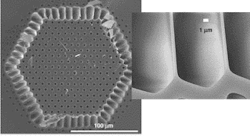
"Endlessly" single-mode fibers also can be made with larger cores than standard single-mode fibers, to reduce power densities and nonlinear effects. One possibility is developing fiber lasers and amplifiers that can withstand higher power levels without reaching the power densities that cause end damage. Recent experiments at the University of Bath (Bath, England) produced double-clad photonic-crystal fibers that when doped with ytterbium operated as lasers with powers to 3.9 W. The outer cladding had a low filling ratio to give a high numerical aperture for the pump beam (see Fig. 3). The inner core had an effective area of 100 µm2. The developers say such lasers could be scaled to higher power.7
Waveguide dispersion can also be adjusted to move the single-mode cutoff to shorter wavelengths and expand the usable transmission spectrum. A group at Crystal Fibre (Birkerød, Denmark) and the Technical University of Denmark has made photonic-crystal fibers with 15-µm cores, chromatic dispersion of 27 ps/km-nm at 1550 nm, and cutoff wavelength shorter than 635 nm.8 The same group has also made a fiber with zero chromatic dispersion moved to the 1064-nm wavelength of Nd:YAG lasers.9 At OFC 2003 (Atlanta, GA) in March, Bath and Blaze Photonics reported making a 100-m fiber with chromatic dispersion nearly flat at 0.5 ± 0.07 ps/km-nm between 1.42 and 1.62 µm.10
Developers are still working out the inevitable tradeoffs. The sensitivity to microbending increases with core diameter, particularly at shorter wavelengths. Shrinking core diameter to increase nonlinearity also increases attenuation. The lowest loss yet reported in a photonic-crystal fiber was an impressive 0.58 dB/km at 1550 nm but that fiber had core diameter similar to those of standard single-mode fibers.11
Photonic-bandgap fiber
True photonic-bandgap fibers have rather different properties arising both from their hollow cores and the nature of true bandgap guidance, but so far they have received less attention than photonic-crystal fibers.
A key difference is that the photonic-bandgap layer blocks light only at certain wavelengths, so light is guided through the hollow core only at those wavelengths. At other wavelengths, the photonic-bandgap layer behaves like a normal transparent material, so light leaks out of the hollow core. Thus, when white light illuminates one end of a photonic-bandgap fiber, only certain colors are guided to the other end.
Guiding the light through air leads to other differences. Air has much lower nonlinearity than glass, and can transmit much higher powers without damage or significant transmission impairments. The material dispersion in air is near zero, but waveguide dispersion in the photonic-bandgap layer can be quite high for wavelengths at the edges of the bandgap. Pure dry air has attenuation of only 0.01 dB/km, but so far no hollow-core fibers have come close to that level.
The lowest attenuation so far in air-core fibers is 13 dB/km at 1500 nm, which Corning reported in a postdeadline paper at ECOC 2002 (Copenhagen, Denmark).12 Its hollow-core fiber had loss below 30 dB/km between 1395 and 1520 nm, a big step beyond the 1000 dB/km of earlier hollow-core fibers. The fiber was made by stacking and drawing hollow tubes. Cracking the 20-dB/km level was also an important milestone for Corning, similar to its first low-loss conventional fiber in 1970.
The Massachusetts Institute of Technology (Cambridge, MA) has demonstrated a different type of hollow fiber, in which the inner surface is clad with a photonic-bandgap structure formed by alternating layers of material with two sharply different refractive indexes. The attenuation is close to 1000 dB/km at 10.6 µm, a number that sounds forbidding, but is lower than that of the materials in the photonic-bandgap structure.13 That technology could be attractive for transmitting high-power laser beams at wavelengths at which conventional fibers aren't available.
Much work remains before either photonic-bandgap or photonic-crystal fibers are ready for practical applications. Producing the lengths of fiber needed for transmission is a difficult challenge. Component applications have the big advantage that they don't require as much fiber, so they seem the most likely to be realized, if developers can find the right balance of tradeoffs.
ACKNOWLEDGMENT
Thanks to James West of Corning (Corning, NY).
REFERENCES
- T. M. Monro, paper at ECOC 2002.
- J. C. Knight et al, IEEE Photon. Tech. Lett. 12, 807 (July 2000).
- J. K. Ranka et al, Optics Lett. 25, 25 (Jan. 1, 2000).
- P. Petropoulos et al, Optics Lett. 26, 1233 (Aug. 15, 2001).
- J. H. Lee et al, IEEE Photon. Tech. Lett. 15, 437 (March 2003).
- J. H. Lee, IEEE Photon. Tech. Lett. 15, 440 (March 2003).
- W. J. Wadsworth, Optics Express 11, 48 (January 2003).
- M. D. Nielsen et al, paper at ECOC 2002.
- P. A. Anderson et al, paper at ECOC 2002.
- W. Reeves et al, Paper FI3, OFC2003.
- L. Farr et al, paper at ECOC 2002.
- N. Venkataraman et al, Postdeadline paper PD1.1, ECOC 2002.
- B. Temelkuran et al, Nature 420, 650 (Dec. 12, 2002).


