Fiber OPAs offer a promising way to tame four-wave mixing
Optical parametric amplification is a nonlinear process that transfers light energy from a high-power pump beam to a signal beam that initially has much lower power. It is most familiar in the laser world as a three-wave mixing process used in optical parametric oscillators, in which pumping a nonlinear material with a strong beam generates outputs at two other wavelengths, called the signal and the idler, that are tuned by adjusting the laser cavity. A recently developed variation on this process takes advantage of four-wave mixing in optical fibers, and could find applications in both amplification and wavelength conversion.
Three-wave mixing is possible in materials with high second-order nonlinearities, but this nonlinearity is very low in silica. However, silica has higher third-order nonlinearity, which makes fibers vulnerable to four-wave mixing noise near their zero-dispersion wavelength. Optical parametric amplification in fiber essentially tames four-wave mixing to shift energy from a powerful pump to other wavelengths. The process is extremely fast and works over a very wide range of wavelengths. Development is still in the early stages, but researchers envision potential applications including broad-spectrum amplification, wavelength conversion, optical time-domain demultiplexing, pulse generation, and optical signal sampling.
Basic concepts
Although the idea of optical parametric amplification in a fiber is not new, net gain on a continuous basis was first demonstrated three years ago. The idea is based on the four-wave mixing process, which generates crosstalk in wavelength-division-multiplexed systems that transmit near the fiber's zero-dispersion wavelength. The interaction of three photons produces a fourth with their frequency related by:
v1 + v2 - v3 = v4
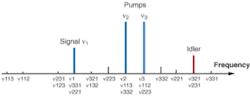
The interaction does not require that all wavelengths be different; in practice, the frequencies v1 and v2 can be identical or different (see Fig. 1).
The physical process behind the interaction is the dependence of silica's refractive index on the light intensity. Changes in the instantaneous electric field—the oscillation of the waves—modulate the refractive index of the fiber, and this index variation affects the light passing through the fiber. The interaction is extremely fast—on a femtosecond scale—and produces side bands of the light being transmitted. The side-band offset depends on the differences between the input wavelengths.
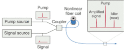
In a simple case, optical parametric amplification in a fiber starts with two wavelengths—a strong continuous pump wavelength, and a weaker signal wave (see Fig. 2). The pump provides two of the photons for the four-photon interactions, so v1 = v2 The signal wave provides the third photon. Either the signal wave or the pump wave can carry information. (The information is what is normally called a signal in fiberoptic systems, but using the word "signal" in both senses would be confusing here).
Pump photons and signal photons combine to affect the refractive index of the glass, while other photons from the pump beam interact with the material. The index variation modulates the transmitted light, producing a pair of side bands offset from the pump beam by the difference between the pump and signal frequency, Δv = v1 - v3. One of these side bands is at the signal frequency, v1 + Δv; the other, called the "idler side band," is at a new frequency, v1 - Δv. This side-band generation amplifies the intensity of the signal wavelength, while creating a beam at the idler wavelength.
The strength of the four-wave mixing effect that creates optical parametric amplification depends on the material's third-order nonlinear susceptibility. It is highest when the fiber has low chromatic dispersion, and near-zero-dispersion slope—exactly the characteristics of zero-dispersion-shifted fiber that make it susceptible to four-wave mixing. Developers have now shifted to special highly nonlinear fibers, which have susceptibility five or ten times higher than conventional zero-dispersion-shifted fiber.
Four-wave mixing does not depend on stimulating emission on particular transitions, so in principle it has extremely wide spectral bandwidth. It does require phase matching of the four waves, but the sum of the phases of the three input waves determines the phase of the fourth wave produced by the mixing process.
Variations on a theme
Early fiberoptic parametric amplifiers could produce net gain only when operated in pulsed mode, making them impractical for most communications applications. Only in a postdeadline paper at OFC 2000 did Jonas Hansryd and Peter Andrekson of Chalmers University of Technology (Göteborg, Sweden) report net continuous-wave gain of up to 38 dB.
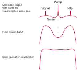
They achieved that result using three lengths of highly nonlinear fiber totaling 500 m, with zero-dispersion wavelengths of 1556.8, 1560.3, and 1561.2 nm. The pump power was about 2 W from an erbium-doped fiber amplifier at 1562.5 nm, in the anomalous dispersion region for the fibers. They used an external cavity laser as their signal source, which could be tuned so they could measure gain as a function of wavelength. They obtained net gain across a range of more than 50 nm, with peak gain for a signal beam at 1547 nm. To show low noise, they modulated the signal beam with a 10-Gbit/s data stream, and measured bit-error rate below 10-9 in the output.
Although those results were encouraging, they showed a large variation in gain over the operating range. To optimize phase matching, the group used a pump wavelength slightly longer than the zero-dispersion point in the fiber. This made phase matching much better at certain wavelengths, producing strong gain peaks above and below the pump wavelength, but with low gain in the middle (see Fig. 3).
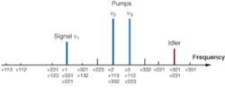
One possible approach is to use a pair of pumps of equal strengths but different wavelengths, so v1 does not equal v2. Combinations of the three input waves can produce output on 12 lines, but power levels are significant only for the two pumps, the signal, and the idler wave. Several arrangements are possible, but simulations by Colin J. McKinstrie and colleagues at Bell Labs (Murray Hill, NJ) indicate that performance should be best if the two pump wavelengths are widely separated, with the signal and idler wavelengths between them. Fine-tuning of pump wavelength and fiber properties is needed to maximize the gain bandwidth.
An alternative is to tailor fiber properties for use with a single pump source. Simulations by L. Provino and colleagues at the Université de Franché-Comte (Besancon, France) show that a combination of four fibers, of varying length and dispersion properties, can produce nearly flat gain across a 100-nm range.
Several other factors also are being studied, with noise levels a particular issue. The mixing process is polarization-dependent, so care must be taken to reduce this. Another key issue is how well fiber parametric amplifiers can handle saturation effects. Prospects for extending bandwidth look good; the best experiments so far have reached 200 nm.
In principle, the noise figure of a fiber OPA can be reduced below 3 dB by using a phase-sensitive design, with the information to be amplified in phase and the noise out of phase. However, Andrekson, now at Leheigh University (Bethlehem PA), warns that phase-sensitive amplifiers may be as difficult to implement as coherent fiberoptic communications, a goal that has remained elusive since it was proposed in the 1980s. So far, most fiber OPA designs have been phase-insensitive.
Applications
Broadband amplifiers are an obvious potential application because the wavelength for optical parametric amplification is set by fiber properties rather than by energy-level transitions. However, researchers have barely begun to explore the possibilities of amplifying multiple optical channels.
Another obvious possibility is wavelength conversion, shifting information from the input to the idler wavelength with amplification as part of the process. The process automatically produces a phase-conjugate of the input signal wave—as the idler—but applications remain speculative.
Fiber OPAs have also been proposed for use in optical limiters, full 3R optical regenerators, optical sampling devices for measurement of high-speed signals, and optical time-domain demultiplexers.
Development is in the early stages. Progress has been enabled by the availability of highly nonlinear fibers and low-cost, high-power pump lasers. Experiments have begun with microstructured photonic fibers, which can provide even higher nonlinearity, but still have high attenuation. Although only a few groups are working today, its prospects are good.
ACKNOWLEDGMENT
Thanks to Peter Andrekson.
BIBLIOGRAPHY
J. Hansryd and P. Andrekson, OFC 2000, Postdeadline paper PD-3.
J. Hansyrd, P. Andrekson et al, IEEE .J. Sel. Topics Quant. Electronics 8 506-520 (May/June 2002).
M.-C. Ho et al, J. Lightwave Tech.19, 977 (July 2001).
C. J. McKinstrie et al, IEEE J. Sel. Topics in Quant. Electronics 8, 538 (May/June 2002).
L. Provino et al, OFC 2002, paper TuS2.