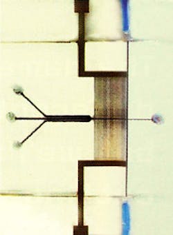
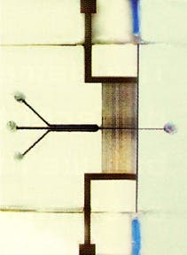
Researchers at National Cheng Kung University and Southern Taiwan University (both of Tainan, Taiwan) have developed several techniques that may make a promising microchip bioanalytical technology practical. These include improved control of samples through the chip using electrophoresis, hydrodynamic control, and robust channel coating; integration of a DNA amplification chamber; and enhanced, easily-aligned optical detection without the need for expensive on-chip electronics.
The new work involves a cytometer, which effectively counts the number of particles (cells) in a sample; and electrophoresis-based separation of fluorescently-tagged specimens, in which an electric field moves different species at different rates, allowing them to be differentiated. Both devices require microchannels through which the sample and buffer solution can flow, electrodes to pull the individual specimens forward, a light source to illuminate the sample, and an efficiently coupled detector. In the cytometer, the detector senses when light is blocked by passing particles. In the electrophoresis chip, fluorescent emissions are picked up to show the relative positions of tagged species.
Until now, one of the biggest problems has been detecting this signal light. In principle, building microsystems to detect or transport the optical signal from the sample is not difficult. In practice, however, it has been difficult to build a system that is efficient and high in resolution without being expensive. The new system is not only cheap in terms of its constituent parts, but has only one manual alignment step—insertion of a fiber into a self-aligning channel.
The buried-waveguide system involves the sandwiching of two low-cost glass substrates, each with identical grooves etched into them, one set for the waveguiding channel and another for the sample flow. The sample channel is orthogonal to the waveguiding channel (which it interrupts). Once these have been aligned, bonded, and fused, the waveguiding microchannel is filled via microcapillary action with a spin-on-glass material and then removed by a vacuum. A coating is left that has two functions: improving the optical surface of the channel, and acting as a cladding layer that provides a high-refractive-index change between core and cladding.
To get light into and out of the system, the ends of two optical fibers were etched so that they would fit into the end of the waveguiding microchannels. The channel is then filled with the core material—SU-8 negative photoresist—to produce the finished optical waveguide. In this way, the sample can be directly interrogated by an off-chip light source, the result of which is read out by an off-chip detector.
For better separation of DNA using electrophoresis, the sample channel was coated with the same spin-on glass as the waveguiding channel. The smoother surface made for better, cleaner flow, and prevented species "bunching." Also, as well as building the electrophoresis electrodes into a third layer of the glass sandwich, the team devised an on-chip heater and temperature sensor for the polymerase chain-reaction (PCR) chamber (where a single DNA strand can be duplicated, effectively amplifying the signals it produces). This temperature control is vital for PCR to take place efficiently. Finally, the team has been working on the shape of the sample channels. The inflow has now been designed so that the sample is effectively focused in the center of the channel by the liquid around it (see figure).
REFERENCE
- Che-Hsin Lin et al., Sensors and Actuators A: Physical 107, 125, 2003.
About the Author
Sunny Bains
Contributing Editor
Sunny Bains is a contributing editor for Laser Focus World and a technical journalist based in London, England.

