PHOTONIC-CRYSTAL FIBERS: Pressure-assisted PCF/SMF splices are low-loss
A very low loss method of splicing photonic-crystal fibers (PCFs) to conventional optical singlemode fibers (SMFs) has been demonstrated by researchers at Chongqing University (Chongqing, China) and the City University of Hong Kong.1 The technique can be used with both solid-core and hollow-core PCFs, and results in splices (at a 1550 nm wavelength) with a loss of 0.40 dB for a splice of solid-core PCF to SMF, and a loss of 1.05 dB for a splice of solid-core PCF to SMF. Such splices should be useful in leading-edge PCF-based communications and sensing systems.
The splices were made using a conventional fusion splicer made by Furukawa Electric (Tokyo, Japan). To achieve such low splice losses, the researchers pump nitrogen (N2) gas into the air holes of the PCF during fusion, precisely adjusting the pressure depending on the characteristics of the PCF.
Two types of PCFs
For the experiment, the researchers chose two different PCFs from NKT Photonics (Birkerød, Denmark). The hollow-core PCF guides light via the bandgap effect, while the solid-core PCF guides light in a singlemode fashion with air as the core’s cladding.
Both types of PCF have a mode-field diameter (MFD) different than that of a conventional SMF; this ordinarily results in a high splice loss. But if the air holes in the PCF are partially collapsed, the MFDs of the two different types of fibers can be made to match. The researchers did calculations that showed, for example, that the collapse ratio for the solid-core PCF has to reach between 0.5 and 0.6 for its MFD to match the 10 μm MFD of the SMF.
For the splice to work, however, the mode-field size transition in the PCF must be a smooth one. This is achieved when there is a smooth transition in fiber temperature along the fiber after the fusion arc discharge, causing the portions of the fiber farther away from the discharge to collapse less gradually as a function of distance.
What is interesting about the new technique is that, unlike previous hole-collapse methods in which the entire PCF was made to shrink in diameter, the N2 gas has enough pressure to keep the outside PCF diameter from changing, while allowing the inner structure to reduce in size to match the MFD of the SMF.
Simulations using full-vector beam-propagation modeling software by Optiwave (Ottawa, ON, Canada) showed that the splice loss for a solid-core PCF to SMF would be lowest if the transition length were to be 20 μm, achieved by a collapse ratio somewhere between 0.457 and 0.592—results that agreed with the researchers’ calculations. Additional modeling showed a spectral loss dependence of the splices that could be minimized by carefully tailoring the splice length and collapse ratio.
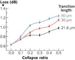
In contrast, for the hollow-core PCF, which confines light only due to the fiber’s photonic bandgap, no air-hole collapse is allowed during splicing, as that would destroy the bandgap effect. This was confirmed by the beam-propagation model, which showed best splice performance with no hole collapse (see figure).
Experiment
Sixteen splices each of the two types were made in the lab, with the N2 pressure optimally about 1.3 bar for the solid-core PCF (which allows partial collapse) and about 1.7 bar for the hollow-core PCF (which completely prevents collapse). In contrast, if no pressure is applied, both types of PCFs show almost complete collapse.
The splice losses of 0.40 dB for solid-core PCF and 1.05 dB for solid-core PCF were both achieved for light passing from the PCF to the SMF; this is the more-difficult direction for a transition. For the reverse (light traveling from the SMF to the PCF), the splice losses were even lower: about 0.1 dB and 0.3 dB for solid-core PCF to SMF and hollow-core PCF to SMF, respectively.
REFERENCE
1. T. Zhu et al., Opt. Exp., 20, 22, 24465 (Oct. 22, 2012).
About the Author
John Wallace
Senior Technical Editor (1998-2022)
John Wallace was with Laser Focus World for nearly 25 years, retiring in late June 2022. He obtained a bachelor's degree in mechanical engineering and physics at Rutgers University and a master's in optical engineering at the University of Rochester. Before becoming an editor, John worked as an engineer at RCA, Exxon, Eastman Kodak, and GCA Corporation.

