Strategic approach limits signal loss and dispersion
Eugene Rudkevich
The incessant demand for more bandwidth has pushed per-channel bit rates of wavelength-division-multiplexing (WDM) fiberoptic telecommunications systems to 10 Gbit/s, and research is currently in advanced stages for channel bit rates of 40 Gbit/s. At 10 Gbit/s, polarization-induced distortion becomes a major limitation in the performance of these systems. Polarization-induced distortion occurs in a fiberoptic communications link possessing any combination of polarization mode dispersion (PMD), polarization-dependent loss (PDL), and polarization-dependent gain (PDG). In addition, interactions between PMD, PDL, and PDG can compound the problem.
Polarization mode dispersion
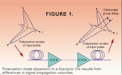
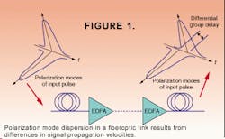
Polarization mode dispersion occurs when the two orthogonal polarization modes in single-mode optical fibers or components propagate at slightly different velocities (see Fig. 1). In silica and erbium-doped fibers, PMD is caused by a statistical deviation from perfect circularity of the core. This induces birefringence in the fiber due to the ovality of the waveguide and the external mechanical stress fields. In fiberoptic components such as isolators and circulators, PMD occurs because of the use of highly birefringent optical elements.
The most serious consequence of PMD in a fiberoptic telecommunications link is pulse broadening, which leads to intersymbol interference, causing an increased bit-error rate. In a section of fiber, the time difference in propagation of the orthogonal polarization modes is referred to as differential group delay (DGD). As a rule, the composite DGD should be kept to less than 10% of a bit period in a fiberoptic link, which translates to 10 ps for a 10-Gbit/s system. This performance penalty is a major limitation for systems operating at 10 Gbit/s and higher.
Polarization-dependent loss
Any component that possesses PDL acts like a polarizer with a very low extinction ratio. That is, given all possible input states of polarization, PDL is defined as the difference between a component's minimum and maximum insertion loss. Polarization-dependent loss occurs mainly in fiberoptic components such as couplers, filters, attenuators, and isolators. This property can degrade the performance of a fiberoptic link because the polarization state of a signal in a single-mode fiber fluctuates with time. Thus, if this signal encounters a component with PDL, the reading at the detector placed after the component will also fluctuate. The component with PDL will induce amplitude modulation.
In fiberoptic test-and-measurement equipment, PDL can limit performance by causing an increased measurement uncertainty due to the random amplitude modulation. In fiberoptic telecommunications systems, PDL by itself is not a significant factor in the system performance; however, when PDL is combined with PDG and PMD in a fiberoptic link, a significant standard deviation in the performance penalty can result. 1
Another interesting effect is that when PDL is combined with PMD in a fiberoptic link, anomalous pulse spreading can result.2 However, it is not yet known whether this phenomenon degrades the performance of fiberoptic networks.
Polarization-dependent gain
In erbium-doped fiber amplifiers the additional polarization phenomenon that occurs is polarization-dependent gain. It occurs when the small signal gain in the polarization mode orthogonal to the mode with the large signal gain is greater than the mode with the large signal gain. Polarization-dependent gain is caused by the polarization dependence of the emission cross section of erbium-doped ions in a silica host (polarization hole burning). When even 0.1 dB of PDG is present in a fiberoptic telecommunications link, the performance degradation can be significant. In addition, PDG interacts with both PDL and PMD to produce an increased standard deviation in the performance degradation of the fiberoptic link. In WDM systems, the combination of PMD and PDG can also lead to amplitude crosstalk between neighboring channels.3
To reduce the deleterious effects of PDG, the polarization of the signal can be scrambled.4 However, polarization scrambling does not completely solve the problem. When the polarization scrambling is below the bit rate of the signal, PDL-induced amplitude modulation and PMD-induced pulse distortion degrade the performance. When the scrambling frequency is higher than the signal bit rate, PMD-induced repolarization leads to degradation of the signal. When the scrambling frequency is comparable to the bit rate, PDL in the fiberoptic link can lead to significant repolarization of the signal and reduced performance.
PMD compensation
In addition to polarization scrambling of the optical signal, sometimes it is also necessary to compensate for PMD and PDL in a fiberoptic link. The basic concept behind PMD compensation is very simple. If one takes two waveplates and orients their fast axes at 90° to each other, the net effect is removal of the retardance in the composite system.
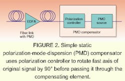
In a similar fashion, a fiberoptic link with PMD is modeled as a waveplate with a very large retardance and some random angle of the fast axis. If a second element with a similar retardance can be inserted in the path and its fast axis can be oriented at 90° to the "fast axis" of the fiberoptic link, the net effect is that the overall retardance is removed and PMD compensation is achieved. A high-birefringence (polarization-preserving) fiber can be used as the compensating element, and a polarization controller can be used to "rotate" the fast axis (see Fig. 2). Recently, more-sophisticated PMD-compensation schemes have been demonstrated.5
PDL compensation
Polarization-dependent-loss compensation works on a similar principle to PMD compensation. In a simplified view, a component with PDL simply acts as a very weak partial polarizer with a typical extinction ratio of 0.1 dB. The object of PDL compensation is to remove the polarization dependence of the component. This can be achieved by inserting a second component into the optical path with an equivalent PDL but with the polarization axis of the second component rotated 90° with respect to that of the first component (see Fig. 3). The composite of the two components acts as an attenuator rather than a polarizer; that is, an input optical signal encounters the same amount of attenuation irrespective of its state of polarization.
The situation is slightly more complicated in a single-mode optical fiber, because the polarization of the propagating signal does not stay constant. The fiber is slightly birefringent. This is due to irregularities in the fiber and external stress or strain induced by bending the fiber. The net effect is that a section of fiber acts like a waveplate with a random retardance and azimuth angle. This presents an additional challenge for PDL compensation, because a component with PDL followed by a section of fiber acts like an elliptical polarizer rather than a linear polarizer. For PDL compensation to work in this case, a polarization controller is inserted into the optical path after the component with PDL and before the equivalent PDL source.
The polarization controller also acts like a waveplate, the azimuth and retardance of which can be adjusted. To perform the compensation, the polarization controller is adjusted so that it has the same retardance as the previous section of fiber, and its azimuth is perpendicular to that of the fiber. In this way, the composite of the component with PDL and the following section of fiber and the polarization controller once again act as a linear polarizer, analogous to the previous section, and PDL compensation is possible.
To implement polarization compensation in high-bit-rate fiberoptic telecommunication systems, one first has to simulate and measure PMD and PDL in a fiberoptic link. To do this, the availability of the enabling components is required. This includes components with a known fixed or variable amount of PMD (PMD sources), components with a known fixed or variable amount of PDL (PDL sources), and polarization controllers. In addition, the polarization controllers must be compact, stable, and easy to adjust.
REFERENCES
- E. Lichtman, J. Lightwave Technol. 13, 898 (1995).
- B. Huttner et al., Opt. Lett. 22, 504 (1997).
- C. R. Menyuk, IEEE Photon. Technol. Lett. 9, 1247 (1997).
- N. S. Bergano et al., Electron. Lett. 32, 52 (1996).
- S. Lee et al., Proc. Optical Fiber Communication, San Diego. CA, TuS3-1 and F. Roy et al., TuS4-1 (1999).
EUGENE RUDKEVICH is president of Taliescent Corp., 10088 E. Paseo San Rosendo, Tucson, AZ 85747; e-mail: [email protected].


