Fiberoptic coupling increases imaging efficiency and view
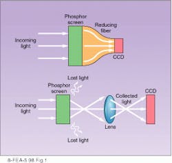
In the majority of charge-coupled-device (CCD) applications, light reaches the CCD through a lens- or mirror-based optical system. However, in some situations it is advantageous to use an image-preserving fiberoptic bundle in place of conventional imaging optics. Significant gains in the amount of light collected from the source can be achieved by directly coupling the light source to the CCD using fiberoptics (see "The big picture"). For instance, an imaging fiber with a demagnification ratio of 2:1 has a collection efficiency 16 times greater than that of an f/1.2 lens (see Fig. 1).
Imaging fiberoptics are commonly used to couple light from x-ray or neutron scintillator screens, chemiluminescent markers, image intensifiers, or streak tubes. Fibers can be bonded to most front-illuminated CCDs as well as some back-thinned devices.
A coherent fiber bundle is a collection of single glass fiberoptic strands assembled together so that the relative orientation of the individual fibers is maintained throughout the length of the bundle. The result is that any pattern of illumination incident at the input end of the bundle re-emerges from the output end with the image preserved. Imaging fiber bundles can be made in a variety of shapes and sizes, with the most common having a circular cross section. Demagnification can be achieved by the use of tapered fibers in the bundle.
To acquire an image, the fiber bundle must be brought into direct contact with both the light source and the CCD. Bonding a large piece of fiberoptic glass to a fragile CCD sensor requires overcoming many technical challenges. Light emerges from the individual fibers at large angles, making it imperative that the distance between fiber and CCD be minimized and consistent. This spacing is difficult to achieve because a typical 25-mm scientific-grade CCD can deviate from flatness by 5 to 35 µm. Larger CCDs can vary even more, sometimes deviating from flatness by as much as 100 µm.
To obtain optimal fiberoptic-coupled CCD performance, Photometrics (Tucson, AZ) maps the CCD`s surface topography, cuts the fiber to a precise fit, and directly bonds the fiber to the CCD without intermediate oil layers or the use of intermediate fiber stubs (fiber bundles with a 1:1 demagnification) that introduce losses in spatial resolution and transmission efficiency. Furthermore, the process produces no bubbles in the bond, and the bond is strong enough to hold up to repeated thermal cycling of the system, important in a cooled CCD camera (see Fig. 2).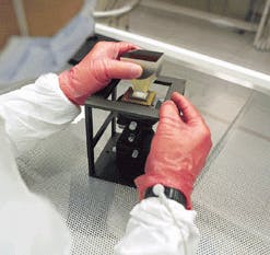
Efficiency vs. demagnification
Besides the transmission losses through a large piece of glass, fiberoptic bundles have a transmission loss due to changes in the fiber diameter as light traverses the bundle. When light travels down a tapered fiber, an increasing reflectance angle results in some of the light paths exiting the fiber. This exiting appears as a loss in effective numerical aperture. The relative loss between fibers with different demagnifications can be estimated as the ratio of their demagnifications squared. The larger the fiber bundle`s demagnification, the greater the reduction in effective numerical aperture. Stubs provide the highest throughput. Applications that require the highest possible collection efficiency often benefit from the use of large CCDs and fiber stubs versus smaller CCDs with higher taper-demagnification ratios. Efficiency also can be increased by bonding to back-illuminated CCDs.
A shortcoming of fiber imaging systems is that the field of view is limited by the size of available fiber bundles. Currently, the largest available tapered-fiber bundle is 165 mm in diameter. However, to enable imaging of even larger areas, a mosaic of fiber bundles that are connected to multiple CCDs can be created. This assembly can either be packaged in a single camera head or into multiple camera heads, depending upon the number of bundles in the mosaic and whether or not the bundles are tapered (see Fig. 3).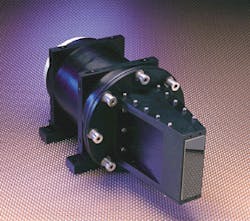
Fiberoptic-coupled CCD cameras are extremely useful for applications that require high light-collection efficiency and are ideal for x-ray nondestructive testing (such as checking for defects in welds) or x-ray imaging (such as mammography). By affixing a phosphor screen scintillator to the fiber bundle, the x-rays are converted into detectable light, which is collected by the fiber bundle. The fiber bundle then efficiently transports the light to the surface of the CCD. The system maintains excellent spatial resolution while protecting the CCD from direct bombardment by the x-rays.
Fiberoptic-coupled systems with phosphor screens also are used for scanning electron microscopy, streak-tube readout, and image-intensifier applications. Transmission electron microscopy makes use of fiberoptic-coupled systems with an yttrium aluminum garnet crystal scintillator to accomplish the same goal.
Bioluminescence and chemiluminescence are applications for which fiberoptic-coupled CCD cameras are particularly suited. No scintillator is needed for the fiber bundles used in luminescence applications, which involve low levels of visible light that require the most efficient collection optics to ensure detection. The image size, the spatial resolution needed for the application, and the nature of the light source in the application dictate the required fiber-CCD combination.
Technology directions
Using a stringently regulated fiber-bonding process allows for the successful bonding of practically any currently available fiberoptic stub or taper to any currently available scientific-grade CCD. However, there are several areas in which fiberoptic performance can be improved. For instance, as mentioned, the largest currently available tapered-fiber bundle is about 165 mm in diameter. Ongoing experimentation with new materials in the manufacturing processes will no doubt raise this limit.
Another limit being re-examined is the temperature at which fiberoptic-coupled technology will work. The present boundary is roughly -60°C, but new bonding techniques and adhesives are being evaluated in an effort to reach the -90°C mark in the near future. More-efficient scintillators, including ones that are integrated into the glass fibers, also have been developed.
As the technology of fiberoptic-coupled CCD cameras continues to grow and improve, so too will the broad array of applications that can benefit from its implementation.
ACKNOWLEDGMENTS
Thanks to Janet Shields of the Marine Physical Laboratory, Scripps Institution of Oceanography, University of California at San Diego, for her assistance and to Photometrics` Rob LaBelle, applications specialist, and Bob Walcott, manufacturing engineering manager, for their input.
The big picture
For more than half a century, the Atmospheric Optics Group at the Scripps Institution of Oceanography`s Marine Physical Laboratory (MPL) has cast its gaze toward the heavens. As part of a research program in atmospheric optics, the University of California at San Diego group has been designing, building, operating, and perfecting whole-sky imager (WSI) systems since the 1950s.
These fully automated, nonemissive, ground-based electronic imaging systems monitor the upper hemisphere, collecting comprehensive data on the presence, distribution, shape, and radiance of clouds over the entire sky. Through the use of preprogrammed cloud decision algorithms and related processing, the WSI system assesses and documents cloud fields and cloud-field dynamics—yielding invaluable information for a variety of purposes, including climate research and military applications.
In the early 1980s, under Richard W. Johnson`s direction, the MPL decided to abandon film as the imaging medium for the WSI in favor of digital technology. The WSI designs used in the 1980s incorporated a solid-state charge-injection-device sensor and a fisheye lens to acquire images. Capturing a full-sky image requires demagnifying the optical image so that it is smaller than the surface of the sensor. To accomplish this demagnification, this earlier version of the system reduced the image size via an optical lens relay.
The WSI system`s extensive data-gathering capabilities were used by the US military in the late 1980s for applications such as creating cloud-free line-of-sight statistics. While these digital WSI systems represented a tremendous improvement over the film-based WSI systems in terms of being able to provide superior sensitivity, reliable linearity over a broader dynamic range, and highly accurate quantitative image data, the WSI remained a daylight-only instrument.
Around the clock
Janet Shields, the principal development engineer who joined the Atmospheric Optics Group in 1971 and now heads the group, notes that there were immediate needs for a digital WSI that could image around the clock. For instance, Shields recalls that in the late 1980s some sponsors were posting their personnel outside with binoculars to report on nighttime cloud conditions. Obviously, this nocturnal method of collecting data left much to be desired.
In the early 1990s, nighttime WSI functionality became feasible. An extremely sensitive, low-noise charge-coupled-device (CCD) camera with a 16-bit digitizer became available, and, instead of relying on an optical lens relay to reduce the size of the optical image, a tapered fiber bundle was used. The higher light-collection efficiency of the fiberoptics in conjunction with the ultrasensitive camera made imaging at night—under either starlight or moonlight—possible (see figure).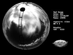
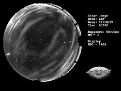
Shields reports that daylight operation of the WSI yields a signal that is only 0.1% noise (shot-noise limited) and that nighttime imaging yields a between-star signal that is just 1.0% noise. The optical quality and spatial resolution of the camera system also are excellent. Shields says that it is the use of this direct fiberoptic bond to the CCD that has made it possible to accurately measure sky and cloud absolute radiance distribution from points on earth—day and night—to assess clouds and cloud morphology over long periods of time.
About the Author
Jeff Grant
Senior Writer, Roper Scientific
Jeff Grant is senior writer at Roper Scientific (Tucson, AZ).