Core alignment for splicing large mode area fibers
Large mode area (LMA) double-clad fibers have a design optimized for use in fiber lasers. Since the core diameter of an LMA fiber is generally larger than the mode field diameter (MFD), LMA fibers can carry a few higher order modes (HOMs). The core diameters of LMA fibers are typically quite large compared to conventional single-mode fibers, and alignment of LMA fiber cores is challenging. Most fusion splicers in the market today are designed for telecom splicing applications.
While some of these telecom fusion splicers are only capable of aligning the fiber cladding (e.g., ribbon splicers incorporating a fixed V-groove passive alignment system), true core alignment telecom splicers are available. These core alignment splicers are in widespread use and provide the capability of aligning the cores of SMF fibers to a submicron accuracy. However, as these splicers are designed for telecom network applications, the core alignment capability only functions properly with standard telecom single-mode fiber types. For LMA fibers, using existing core alignment algorithms results in either an error message, or random, inconsistent, unreliable core alignment.
Octagonally clad LMA fibers have been developed to meet specific needs for the “active” fiber in high-efficiency fiber lasers. Octagonal LMA fibers are now predominant for nonpolarized active LMA fibers, because the octagonal shape promotes effective coupling of all cladding pump power modes to the LMA core. If the active LMA fiber is nonpolarized, any pump power in a helical cladding mode may not couple to the doped LMA core unless at least one flat surface is provided on the surface of the cladding. Various cladding shapes have been tried, such as two flat surfaces on opposite sides of the cladding, hexagonal cladding shapes, etc. However, the octagonal shape is now almost an industry standard. Unfortunately, the octagonal shape presents additional challenges for core alignment.
For telecom fibers, modern industry standards dictate that the core-to-cladding concentricity error (CCCE) of standard SMF may be no greater than 0.5 µm. Such a tight CCCE tolerance is difficult to achieve with LMA fibers because cladding diameters are generally larger (e.g., 250 μm or 400 μm) and fiber production volumes are low. Controlling the CCCE of active octagonal LMA fibers is further complicated by the octagonal cladding geometry. As a result, it is not uncommon for LMA fibers to have a CCCE of 1.5 µm, and sometimes the CCCE is significantly higher. The implications of the core/cladding concentricity error are that when the claddings of two LMA fibers are aligned, the result may easily be a core misalignment of 3.0 µm or more, whereas cladding aligned standard SMF can have a maximum resulting core offset of 1.0 µm.
If LMA fibers are spliced together using cladding alignment, negative performance characteristics may be introduced at the splice point. Effects of core misalignment at the splice point present themselves via coupling of the core signal to cladding modes or, more likely to modes within the core. Since LMA fibers are double-clad, cladding modes may continue to be guided by the (inner) cladding. This cladding power may result in downstream heating of the fiber and present thermal management problems if the misalignment of the cores is particularly bad and if the power level is high. In any case, such cladding modes are undesirable at the output of the fiber laser and should typically be eliminated by a cladding mode stripper. Higher-order modes are a more significant problem because they may degrade the fiber laser beam shape and result in application-specific performance problems. For example, higher order modes may focus on a different point from the primary mode in the output of the fiber laser, degrading performance in a cutting or engraving application. These issues make LMA fiber core alignment highly desirable.
For general telecommunications network splicing of SMF, the principal concern is attenuation of the optical signal and splice loss. For splices of LMA fibers in a fiber laser, attenuation or splice loss may be difficult to measure. Important performance considerations for fiber lasers are thermal management, laser output power, and beam quality. While a typical expectation or requirement for telecom network core alignment splicing with SMF might be 0.2 µm, a more common goal among many fiber laser manufacturers is to align the cores of LMA fibers within 1.0 µm, especially for larger diameter LMA fibers. Such performance would be almost equivalent to that achieved with common SMF when considered as a percentage of the total CCCE that might otherwise degrade core alignment.
Profile alignment system, IPA, and IPA2
The Profile Alignment System (PAS) was developed to detect and align the cores of standard SMF and is commonly used for telecommunications network splicing.1 It has matured into a technology with the ability to analyze the rotational position of a fiber, identify its type, and compare it to the fiber to which it is being spliced.
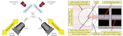
A PAS fusion splicer is arranged on an (X, Y, Z) coordinate plane where high-resolution cameras are aligned on the X and Y axes, and the fiber occupies the Z axis. Each camera has a corresponding LED along its axis on the far side of the fiber, which provides collimated light that passes through the fiber and is detected by the camera. This PAS system arrangement is shown in Figure 1a. The collimated light that passes through the fiber refracts wherever a difference in refractive index is encountered. As the light passes from the air into the cladding of the fiber, it bends inward toward the center of the cladding. Some of that light encounters the core of the fiber, where it is refracted inward again by the difference in refractive index between the core and the cladding. In Figure 1b, the refraction of the illumination light is shown for a standard G.652 telecommunications SMF along with the resulting fiber image.
The inward refraction of the collimated LED light results in an image unique to each fiber construction. At the extreme edges, the background brightness of the splicer’s LED is visible where the illumination light from the LED is unimpeded by the presence of the fiber. This defines the outline of the fiber and enables the splicer to measure the cladding diameter, the cleave angle and shape, and the angle of the fibers relative to one another. In addition to collecting data measured through observation of the fiber cladding, the PAS system adjusts the camera focus plane for optimal detection of the SMF fiber core position (see Fig. 1b).
To succinctly define the focal plane location, an observable focus ratio is created. This is the ratio of the width of the bright center region of the fiber image relative to the fiber’s diameter. For example, when the width of the bright center region occupies ¼ of the total fiber diameter from cladding edge to cladding edge, the focus ratio is said to be 0.25.
At an optimal focus ratio, this bright inner region displays a set of recognizable lines that serve to indicate the location of internal fiber geometry. A dataset is then extracted from the optimally focused image wherein the brightness intensity of the image pixels is plotted against the lateral pixel position across the fiber. The resulting data can be plotted as a brightness intensity profile (see Fig. 2), where the horizontal axis of the graph is the lateral position across the diameter of the fiber and the vertical axis is the corresponding brightness intensity of the image at that point.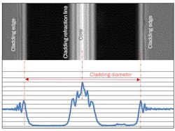
In the case of standard telecom SMF, the position of the fiber core within the cladding is easily determined by detection of a brightness peak within the bright central area of the fiber image. This bright core peak is easily observable when the camera focus position is optimized and reveals the location of the core within the cladding. The core brightness peak is identified in the PAS camera image in Figure 1b and can be easily seen at the center of the blue brightness intensity profile plotted at the bottom of Figure 2. In practice, the optimum focus ratio may be determined experimentally for a given fiber type and entered into the splicer as a parameter, or the splicer can use a search routine to adjust the focus and find the position that results in the most clearly identifiable core brightness peak.
Analysis of a fiber’s brightness intensity profile is the essence of PAS and serves as the basis for further developments to enable the application of PAS for purposes other than alignment of the cores of single-mode fibers. If the PAS dataset is plotted against the fiber’s rotational position, a new set of functionalities is realized. If a perfectly symmetrical fiber is rotated in view of a PAS camera, its brightness intensity profile will not change—regardless of rotational position. By contrast, if a fiber having any refractive index or other asymmetry (such as a polarization maintaining fiber) is likewise rotated, its brightness intensity profile will change as a function of the changing rotational position. The light refracting through the rotating internal geometry of the fiber generates a different brightness intensity profile for each angular position, highlighting internal symmetries and differences of the fiber. This effect is highly pronounced in fibers with well-defined planes of symmetry.
While the brightness intensity profile at different rotational positions can be used in many ways, one effective method is to interrelate the PAS data with the fiber’s rotational position. Observing some characteristic from the PAS brightness intensity profile at successive rotational positions produces a new set of data that can be used to interpret the rotational position of internal features of a fiber. This method is formally referred to as Interrelation Profile Analysis or IPA.2 It should be noted when IPA is used, there may not be an observable core peak within the bright central area of the fiber image.
With most polarization-maintaining (PM) fibers, the core position is not detectable regardless of the fiber’s rotational orientation. However, other data within the brightness profile may be collected and plotted relative to rotational position. Precisely which characteristic from the brightness intensity profile is used for IPA is proprietary and will not be discussed here.
A characteristic IPA data plot for a Panda PM fiber is shown in Figure 3, and the corresponding rotational orientation of the Panda fiber is shown underneath the IPA data. The IPA profiles for the left and right PM fibers can be compared and correlated to each other directly (in the case of similar left/right PM fibers) to determine how far to rotate one or both fibers to ensure the best alignment of the polarization axes of the two fibers. If the two PM fibers to be spliced have different characteristic IPA profiles, the IPA data for each fiber may be indirectly correlated to IPA profiles stored within the splicer’s IPA database.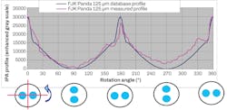
Using IPA as a method of aligning asymmetrical and other rotationally sensitive fibers is tremendously powerful and enables a wide array of splicing possibilities. But the originally developed IPA did not work well for alignment of some PM fiber types. More recently, a new version of IPA, IPA2, was developed. IPA2 operates in a manner analogous to IPA, but the way data is observed and plotted and how fibers are observed during rotation is different. IPA2 provides improved rotational alignment accuracy for many types of PM fibers.
Application of PAS and IPA2 techniques to LMA fibers
While LMA fibers are similar in structure to common telecom SMF (with a pure silica cladding surrounding the higher index of refraction core), there are significant differences. The major design differences between SMF and LMA fibers are not only the large diameter of the LMA core, but also the lower refractive index difference between the core and inner cladding of the LMA fiber.
In the case of a standard SMF, a well-defined brightness peak is easily observable in the PAS image near the center of the bright area, and this reveals the core position. The large core diameter of the LMA fiber results in a PAS image with two dark parallel lines, but without a well-defined core brightness peak. The lower refractive index difference of LMA makes the core refraction line much dimmer than the SMF structure and more difficult to distinguish from the background noise. To accurately locate the core of LMA fibers, the focus ratio should be carefully chosen to avoid camera saturation—while also providing adequate resolution to differentiate the core refraction line from background noise. But even with precise optimization of the focus position, the core peak for LMA fibers is still more difficult to accurately detect. Since the core detection methods adequate for common SMF are unreliable for LMA fiber, it is necessary to develop new proprietary core alignment algorithms to enable LMA core position detection.3
Passive LMA fibers are quite similar in structure to standard SMF, having a round pure silica cladding containing a higher index core. The new LMA core alignment algorithm enables core alignment of the passive fibers, but a further problem arises with fibers of a noncircular cladding shape. Random rotational orientation of the noncircular fiber shape relative to the splicer’s camera system results in random refraction of the illumination light that passes through the fiber, and no consistent or discernable image will be achieved.
IPA2 provides a solution for octagonally clad fibers. While IPA was originally developed as a method to rotationally align the polarization states of PM fibers, an IPA2 alignment mode is provided to rotationally align an octagonally clad fiber such that flat surfaces of the octagon are perpendicular to the orthogonal X and Y camera observation axes of the splicer. This enables the PAS system to observe a consistent fiber image. An IPA2 profile for an octagonal fiber is shown in Figure 4a. The IPA2 data is clearly periodic to 45 degrees of rotation, which enables simple rotational alignment of the octagonal fiber relative to the splicer’s camera system.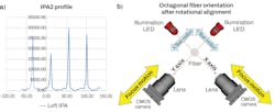
While PAS core alignment capability was previously only applicable to cylindrically clad fibers, with the introduction of the new IPA2 rotational alignment mode for octagonal fibers, it’s now possible to apply core alignment to octagonal active LMA fibers. Once IPA2 is used to rotate the octagonal fiber such that flat surfaces of the octagon are perpendicular to the camera axes (see Fig. 4b), a useful PAS image is available. This permits the light to travel through the fiber and displays a brightness intensity profile that allows detection of the core location via the new LMA core recognition technology. And this enables the core of an octagonal active LMA fiber to be aligned to the core of the cylindrically clad passive LMA fiber. Regardless of the random angular rotational orientation in which the octagonal fiber has been loaded into the splicer, IPA2 enables the cladding to be rotated to the correct position for core alignment.
In Figure 5, the brightness intensity profile of an octagonal active LMA fiber was overlaid over the passive (round) LMA fiber to which it is being spliced. IPA2 was first used to rotate the octagonal fiber to the proper position relative to the splicer’s cameras. By using the new LMA core alignment technique, a core brightness peak is observable near the center of the bright region of the brightness intensity profile of both octagonal and round LMA fibers.
Core alignment and verification for LMA fiber splicing
The core offset repeatability test is a frequently used method for quick analysis of the quality of a core alignment algorithm. Using identical fiber types on the left and right of the splicer, alignment data is collected by either (a) performing core alignment while measuring cladding offset (misalignment) or (b) performing cladding alignment while measuring resultant core offset.
Repetition (without re-cleaving or reloading the fibers) enables verification of the consistency and repeatability of readings. For this test method, at least one fiber in the pair should have sufficient CCCE to enable measurements not within the noise level of the measurement system. Moreover, one of the fibers should be rotated to search for the maximum core offset between the left and right fibers. Test results are shown in the table for four LMA fiber types.
The data in the table shows alignment repeatability for round passive LMA fibers. For splicing an active octagonal LMA fiber to a round passive fiber, it is not possible to use the same method as above because the octagonal fiber cannot be rotated to search for maximum core offset. This is due to the need to use IPA2 to rotate the octagonal fiber to the specific angle required to enable PAS core observation. When tested in the lab, the repeatability of the angular alignment of the octagonal fiber was within a few tenths of a degree, indicating the rotational orientation of the octagonal fiber by IPA2 is repeatable. Subsequent core alignment using the new LMA core alignment capability showed results consistent within 1 µm when cladding misalignment of nearly 4 µm was required to align the LMA cores.
It’s significantly more difficult to align cores of LMA fibers compared to cores of standard SMF. The greater variability of CCCE in LMA fiber, the low contrast between core and cladding, and issues concerning cladding geometry present significant challenges to core alignment with PAS. Accordingly, the same submicron core alignment accuracy typical for splicing common SMF fiber isn’t achieved with LMA fibers. Nevertheless, by using LMA core alignment algorithms, optimizing the camera focus position, and rotationally aligning the cladding of active octagonal LMA fibers using IPA2, laboratory testing demonstrated core alignment performance for LMA fibers with good repeatability. While the precision of LMA fiber core alignment does not match that for common SMF, it is similar as a percentage of possible CCCE.
Although the magnitude of the benefits need to be quantified by implementing these LMA core alignment capabilities in fiber laser production, the LMA core alignment capability should provide benefits for fiber laser manufacturing such as improved thermal management, better beam quality, and generally, better and more consistent fiber laser performance. The new LMA core alignment capabilities will be further refined as more experience and user feedback is gained via implementation in fiber laser production applications.
REFERENCES
1. Duke and D. Mansperger, Issues Concerning Dissimilar Single Mode Splicing, Proceedings of the 66th International Wire & Cable Symposium, 648–656 (2017).
2. W. Zheng, D. Duke, T. Kubo, and B. Malinsky, Interrelation Profile Analysis Method for Alignment of Polarization-Maintaining Fiber, OFC/NFOEC 2010, OSA (2010).
3. W. Zheng and D. Duke, Core Alignment for Large Mode Area Fibers, Photonics West 2022, Paper 11981-72 (2022).
About the Author

Doug Duke
Senior Applications & Development Engineer
Doug Duke is a senior applications and development engineer in splicer engineering at AFL. After receiving his Bachelor of Science in Mechanical Engineering from the University of Texas at El Paso, Doug joined the Defense Systems and Electronics Group at Texas Instruments and worked primarily in the development of airborne radar and infrared detection systems. Since joining AFL in 1991, he has worked continuously in engineering activities related to fusion splicing of optical fibers. In his more than 25 years as a splicing engineer at AFL, Doug has guided splicer product development, authored and presented numerous technical papers, conducted seminars on fusion splicing technology and applications, and is named in several patents.

Craig MacMillan
Applications Engineer, R&D, Splicing Division at AFL
Craig MacMillan is an application engineer for fusion splicers and accessories at AFL (Duncan, SC). He earned a Bachelor of Science in Physics from The Citadel, the Military College of South Carolina, with a focus in optical sciences. As an application engineer, he works alongside sales, repair, and customers to solve day-to-day splicing challenges experienced in the field.