When testing transmitters, think like a receiver
GREG LeCHEMINANT
Although there are many properties of an optical transmitter that help describe its ability to operate in a high-speed digital communications system, the simplest way to quickly gauge performance is to view the output waveform as a function of time on a wide-bandwidth sampling oscilloscope. The most useful way to view this waveform is in the eye-diagram format, which superimposes the shapes of all of the waveform's bits on a common time axis. Rather than showing a few sequential bits of data, the eye diagram gives information on all the bits and transitions in the complete data pattern. By superimposing the data on a common time axis, usually less than two bit periods in width, the overall performance of the transmitter for virtually any data sequence can be seen in a single view.
The eye diagram
With experience, most engineers and technicians can look at an eye diagram and tell if it is "good" or "bad." However, when it comes to verifying that a transmitter complies with an industry standard, beauty is in the 'eye' of the beholder. In the case of a high-speed communications system, the perspective that really counts is that of the receiver that will take the signal and try to turn it into clean ones and zeros.
Key requirements for the transmitter stem from two primary receiver requirements. First, the receiver needs the signal to have good amplitude separation (or wide separation between logic ones and logic zeroes). Noise is present in all communications systems, and a signal must be strong enough such that when this noise is added to the transmitted bits there will still be a large separation between logic levels at the receiver decision circuit. Second, the receiver needs a low jitter signal (the relative time location of transitions between ones and zeroes should be consistent). These two characteristics help ensure that it is easy to differentiate between the amplitudes that represent ones and zeroes, and that decisions about the value of a given bit are made in its center, where it is very unlikely that the value of the bit will be misinterpreted.
Good amplitude separation and low jitter are seen as an open eye diagram (see Fig. 1). The openness of an eye diagram can be verified by performing an eye-mask test. A mask consists of several polygons that are placed in and around the eye diagram, indicating areas where the waveform should not exist. A "good" waveform will never intersect the mask and will pass the mask test; a "bad" waveform will cross or violate the mask and fail.
Passing the mask test
If the receiver's perception of the waveform is critical, then it is important to find a way to do the mask test from the perspective of the system receiver. For many years, the concept of a reference receiver has been the foundation of standards-based optical transmitter test. A reference receiver is an optical-to-electrical converter with a fourth order Bessel-Thomson frequency response whose -3-dB bandwidth is set to a frequency of 75% of the transmission data rate. For example, if the transmitter operates at 10 Gb/s, the reference receiver bandwidth will be 7.5 GHz. The reference receiver is used to give the test system the desired communications system receiver perspective.
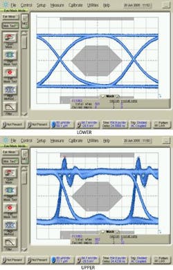
If the bandwidth of an oscilloscope system attenuates the frequency content of a signal, it will not provide a completely accurate representation of the signal waveform. In almost all cases, a bandwidth less than the data rate will significantly alter the shape of a digital communications waveform. If a laser transmitter operating at 1.25 Gb/s is measured with a 10 GHz optical oscilloscope and no reference receiver, the eye-diagram signal—when viewed with a 10-GHz bandwidth setting—shows significant overshoot and ringing (a common phenomenon with high-speed laser transmitters). The overshoot is so severe that the waveform fails the mask test. However, when the same oscilloscope is configured with a 1.25-Gb/s optical reference receiver (938 MHz bandwidth), the high-frequency content of the signal is suppressed, the signal appears to be very well behaved, and the waveform easily passes the mask test.
The use of a reference receiver seems counterintuitive, because it appears to have cleaned up the true behavior of the laser and possibly made a bad device look good. This is where it becomes important to take a step back and remember the goal of testing. The goal is not to precisely characterize the behavior of the laser; rather, the test is intended to determine how well the laser will interoperate with a receiver in a real communications system. System receivers will not have infinite bandwidth, so it does not make sense to test the transmitter as if it were communicating with a receiver that did. Instead, receivers often have just enough bandwidth to correctly differentiate a logic one from a logic zero. For a non-return-to-zero (NRZ) signal the ideal system bandwidth for this will be near 75% of the data rate—the bandwidth used by the reference receiver. Thus the test system reference receiver provides a good representation of the signal from the perspective of a system receiver. Additionally, a reference receiver provides consistency in test: if everyone tests with a specific measurement-system bandwidth, results should not vary between test systems.
As was mentioned earlier, it is important for the signal strength of a transmitter to be large enough to overcome the noise present in a system. It is also important for the signal to be strong enough to maintain distinct logic levels after traveling a long distance. Early optical high-speed communications systems often spanned large distances, and required repeaters to overcome channel attenuation. It was important to maximize the available power from laser transmitters.
Laser signal strength and integrity
One measure of the communications efficiency of a laser is the ratio of the 'one' level to the 'zero' level. This measurement is called extinction ratio (ER). Consider a transmitter that sends logic ones at a level of 1 mW and logic zeroes at 0.1 mW. Consider another transmitter that sends ones at 1.5 mW and zeroes at 0.6 mW. From the receiver perspective—where amplitude separation is critical—both transmitters would perform equally well, because both have a separation of 0.9 mW. However, the second transmitter requires significantly higher power to achieve that separation. The first laser has an ER of 10 and is far more efficient than the second laser, which has an ER of 2.5. The extinction ratio is used as an indicator of how well available laser power is converted to modulation power. High extinction ratios are usually achieved by forcing the zero levels close to a no-power state. Historically, pushing the denominator of the ER to such a low value has made it difficult to measure large extinction ratios with high accuracy, because small variances caused by imperfections of instrumentation can result in large changes in the derived ER. To address this problem, new calibration techniques have been developed to allow more accurate testing of high-ER transmitters.
As laser transmitter technology improved, lower-cost transmitters became available, and high-speed optical local area networks (LANs) have become practical. Due to the relatively short spans of such systems, laser efficiency becomes less critical. However, it is still important to maintain a good separation between ones and zeroes for the receiver. This can be measured directly as the optical modulation amplitude (OMA), which is computed by taking the difference in the amplitude of the one and zero levels. In the previous examples, both lasers have OMA values of 0.9 mW, and both might be considered equally good for a LAN.
High-speed signals and BER
As speeds increased up to and beyond 1 Gb/s, the timing stability of signals became more difficult to manage. Timing jitter, observed when signal edges are not consistently located in time, leads to decision circuits not making their decisions in the center of the bit. As edges drift towards what should be the ideal decision time, and the receiver begins to make decisions about bits by measuring amplitudes at a point along those edges instead of at the center of the bit, the bit-error ratio (BER) is degraded. To avoid this, transmitter jitter must be controlled to manageable levels, and once again the capabilities of the receiver dictate what this level should be.
Receivers require a clock signal to time their decision process. Many receivers derive this clock directly from the incoming data stream through some form of clock extraction circuit. The clock extraction process provides some tolerance to transmitter jitter, because the receiver clock extraction circuitry can track and follow jitter in the incoming data stream, as long as the jitter is not too fast. Typically, if the rate of the jitter is within the loop bandwidth of the clock extraction circuit, the receiver will tolerate it.
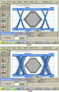
If the receiver is tolerant to lower-rate jitter, it does not make sense to reject transmitters that have jitter at these low rates. In recent years, communications standards have been designed to account for this. The oscilloscope used to measure jitter is specified to have a high-pass jitter function so that test results are not impacted by the presence of low-frequency jitter. The easiest way to produce a jitter high-pass function is to derive the oscilloscope triggering from the observed waveform, in a manner similar to how the receiver derives its clock. This is often referred to as "Golden PLL" testing. A clock recovery circuit with a specific loop bandwidth is built into the oscilloscope, allowing it to generate timing (or triggering) signals similar to those generated by a system receiver. When the test system employs the correct Golden PLL bandwidth, the test system mimics the system-level receiver and eliminates low-frequency jitter, as low-frequency jitter is common to both the oscilloscope trigger and the observed signal (see Fig. 2). Both measurements are of the same signal, but the Golden PLL waveform, using the clock extraction circuit with the correct loop bandwidth, provides a better assessment of the waveform from the perspective of the receiver it will be paired with.When dispersion dominates
Efforts are currently under way to transmit signals as fast as 10 Gb/s over channels where dispersion dominates system performance. The modal dispersion for installed bases of multimode fiber with distances in the 200- to 300-m range can completely close the received eye. Advanced communications techniques will be required to overcome the large signal dispersion problem, and receivers will likely have equalization schemes to compensate for the impairments caused by the channel. This complicates the definition of what an acceptable transmitter might be. For example, eye-mask testing may prove to be of small importance if the eye at the output of the channel is closed no matter what the signal quality is going into the channel.
One approach being used by the Institute of Electrical and Electronics Engineers (IEEE; www.ieee.org) in their standard, IEEE 802.3aq, '10-Gb/s transmission over FDDI-grade fiber,' is to measure how "equalizable" a transmitter is. The transmitter waveform is captured and run through a virtual channel model, which simulates actual fibers. The virtually dispersed signal is then passed through a virtual finite-length equalizer. The equalized signal is then compared to the quality of the signal if it had been passed through an ideal equalizer. The general theme for transmitter test is maintained; that is, the transmitter is tested from the perspective of the receiver. However, in this case the receiver is highly sophisticated using both linear- and decision-feedback equalizers with several signal taps.
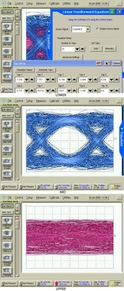
To illustrate, a dispersed signal is captured by the oscilloscope and passed directly into a mathematical description of an equalizer within the oscilloscope (see Fig. 3). The equalized signal is displayed in 'real time' on the oscilloscope, showing how the highly dispersed signal is nicely recovered (a recognizable 'eye' in the eye diagram) with the oscilloscope equalizer. The equalizer can be user-defined (number of taps and tap weights) or automatically designed by the oscilloscope.Testing transmitters has evolved to accommodate changes in both system architecture and performance. Currently, speed increases and the pushing of channels to operate beyond their original expected performance have complicated transmitter testing. However, the general approach of viewing signals from the perspective of the receiver has stood the test of time, and it is likely that it will continue to play an important part in testing transmitters designed to work with even the most complicated channels and receivers.
Greg LeCheminant is a measurement applications specialist with the Digital Verification Solutions Division of Agilent Technologies in Santa Rosa, CA; email: [email protected].


