MICRODISPLAYS: Infrared scene projector provides realistic threat scenarios
JULIA RENTZ DUPUIS
As more sophisticated infrared (IR) threat-detection systems are developed there is an increasing need for more-realistic and versatile IR scene generators to exercise the detectors' discrimination capabilities. Infrared scene generators represent a cost and environmental-footprint savings relative to more traditional test equipment such as large propane torches or live-fire testing of in-flight missile warning systems (MWS).
Advanced threat-detection approaches typically utilize two midwave-IR (MWIR) bands in the vicinity of 3 to 5 µm to discriminate between carbon dioxide emitting threats and non-threat natural and manmade objects. More specifically, the intensity ratio of the two bands, loosely called "blue" and "red," varies in a characteristic manner during the flight of the threat. New IR scene generators therefore must be able to simulate events in which the intensity ratio between blue and red bands can be varied over the duration of the scene. In addition, the IR scene generators must meet radiant intensity, switching time, radiometric and spatial resolution, and scene-duration requirements representative of an actual missile flight.
Technical approaches to IR scene generation vary and include resistive arrays, laser and LED arrays, and liquid-crystal and digital-micromirror-device (DMD)-based systems.1-5 Resistive arrays, the most prevalent technology, are essentially bolometric arrays in which current is driven through individual pixels to make each radiate at an individually addressable intensity. Laser and LED arrays often use a scanner component to cut down on the number of lasers or LEDs required. Scene generators using spatial light modulation (SLM), such as liquid crystals and DMDs, typically use a thermal source in place of a visible source in a traditional digital light projector and create the spatial scene with the SLM.
Digital-micromirror devices are composed of hundreds of thousands of micromirrors in a format comparable to that of a CCD array. Each micromirror flips between "on" and "off" positions corresponding to ±12° tilt angles about the diagonal of the micromirror; the on position directs radiation from the source out through a projector optic, and the off position directs it toward a beam dump or light trap. Grayscale resolution is accomplished by pulse-width modulation of each micromirror, which essentially means variation in the duty cycle of the micromirrors in their on-versus-off positions.
Two bands instead of one
Scene generators using any of these technologies conventionally tend to have a single spectral band, which is either very broad in the case of resistive arrays and SLM-based systems or relatively narrow in the case of laser or LED arrays. The projection of the two independent spectral bands used by threat-detection systems, as well as the ability to vary the intensity ratio between the two bands, represents an advanced capability in IR scene generation.
We are undertaking the development of a two-band IR scene generator based on the DMD approach. This system uses two DMDs—one for each spectral band—and a series of MWIR lenses and filters to overlay and project the two spectral images to a unit under test (UUT). Because we are not changing the IR source temperature, response can be faster than resistive-based simulators; in the same vein, thermal-management issues are less complex than with resistive arrays whose time constant depends on it. Simplified thermal management may result in a lower-power, more fieldable system. At the same time, this approach provides a broadband simulation, unlike laser or LED simulators, resulting in a more representative target on which the threat-detection system trains. The overall approach offers a realistic IR source image of characteristic spectral, temporal, and radiant intensity properties of a typical airborne threat.
Scene-generator description
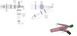
Two miniature thermal sources are used to illuminate two DMDs with a telecentric Koehler configuration (see Fig. 1), meaning that the chief rays for all points across the DMD are collimated (telecentric) and the DMDs are illuminated at a field point rather than a source image (Koehler illumination).
This combination results in maximum radiometric throughput and good illumination uniformity. The spectral channels are set by a bandpass filter in each illumination module and are in the vicinity of 3.8 to 4.1 µm (blue) and 4.5 to 4.7 µm (red). The illumination is at 24° incidence where the DMDs are normal to the projection axis encouraging the best quality of the projected images. With the micromirrors in the "on" position, the source light is reflected by each micromirror in each DMD toward a dichroic beam combiner followed by a (telecentric) projector lens that forms an image of the DMD at infinity. When the micromirrors are in their off position, the source radiation is directed onto a beam dump (not shown). Because the grayscale level of each micromirror in each DMD is individually controllable, we can vary the ratio of the images projected in the two bands as a function of scene duration. A UUT placed in the projected beam then images the DMD onto its focal plane(s) and executes the discrimination calculations.
Performance projections
Figures of merit for IR scene projectors include maximum radiant intensity, grayscale and spatial resolution, switching rate, and maximum scene duration. The projected beam diameter also must fill the aperture of the UUT. In general, threat-detection systems are working with spatially unresolved targets (that is, the image of the threat is much smaller than a UUT pixel); IR scene generators can therefore project a highly collimated beam with a very small internal field of view (IFOV) per micromirror (or group of micromirrors). If the projector optic can be chosen such that, with throughput matching, a maximum radiant intensity requirement is met, the maximum radiant intensity then becomes solely dependent on the IR source temperature, and of course the radiometric efficiency of the rest of the projector system. In other words, the collimation of the projected image can be increased to increase the number of watts per steradian if required. The maximum radiant intensity in watts per steradian is then given bywhere εs is the IR source emissivity (unitless), η is the radiometric efficiency of the scene generator (unitless), N(λ,Ts) is Planck's blackbody function at the source temperature, Ts, spectrally integrated over the red or blue band (units of W/(cm2ster) following the integration), and Ap is the projector optic area (units of cm2). The OPTRA scene generator employs a 750°C source with an emissivity of 0.95 in the red band; the radiometric efficiency is analytically predicted to be 0.4, and the projector area is 78.5 cm2 (10 cm diameter). The maximum radiant intensity in the red band is about 1 W/ster.
The rest of the performance parameters are determined by the DMD chipset and controller electronics. The simulator uses a Texas Instruments Discovery 1100 kit with a Digital Light Innovations ALP2 daughter board with 64 Gbit of RAM. With this combination, 10-bit images can be generated at a frame rate of 40 Hz for scene durations of up to 54 s. The DMD has the standard 1024 x 768 micromirrors; however, we are only using a circular portion with a 768-micromirror diameter. The IFOV associated with a single micromirror is 43 µrad, however, the minimum projected object size is equivalent to five micromirrors, or 220 µrad. The window on the DMD is replaced with an IR-transmissive calcium fluoride window.
IR scene simulations
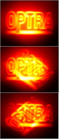
A simulation was carried out using a breadboard version of the two-band generator. The projected scenes were imaged using a FLIR Systems SC4000 indium antimonide (InSb) camera. In the experiment, the images projected by the red and blue channels were overlaid. The image projected by the red channel was then rotated clockwise relative to the blue channel, and, alternatively, the image projected by the blue channel was rotated counterclockwise relative to the red channel. Still frames taken from the simulation illustrate the ability to independently control the two bands (see Fig. 2).The breadboard was also used to verify our analytical models predicting maximum radiant intensity, grayscale resolution, and image registration.
ACKNOWLEDGMENTS
This work is supported through a U.S. Navy Phase II SBIR contract number N68936-07-C-0024.
REFERENCES
1. J. Oleson et al., Proc. SPIE 6208 (2006).
2. D. A. Saylor et al., Proc. SPIE 6942 (2008).
3. N. C. Das, Proc. SPIE 6208 (2006).
4. M. A. Handschy et al., Proc. SPIE 6208 (2006).
5. D. B. Beasley et al., Proc. SPIE 6208 (2006).
Julia Rentz Dupuis is a senior scientist at OPTRA Inc, 461 Boston St., Topsfield, MA 01983; e-mail: [email protected]; www.optra.com.


