Intensified charge-coupled devices (ICCDs), developed mainly for military night-vision devices, have come into their own as fast, highly sensitive scientific instruments. They combine the high resolution and relatively low cost of CCDs with the enhanced sensitivity of image intensifiers, which can also gate device response to time windows as narrow as 2 ns. As a result, these detectors now find use in applications such as laser-induced fluorescence, laser-induced breakdown spectroscopy, and single-molecule fluorescence imaging.
Decomposing ICCDs
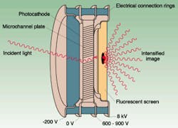
An ICCD consists of an image intensifier coupled to a CCD (see Fig. 1). The core of the image intensifier is a type of photomultiplier tube called a microchannel plate (MCP). According to engineers at Roper Scientific (Trenton, NJ), this device has an array of millions of parallel channels, each several microns across—6 µm is a typical size. The channels, which are carved into a glass substrate about 2 cm in diameter and 0.5 cm thick, are coated with a secondary electron emitter such as cesium iodide or copper iodide. When an electron hits the side of the channel, the device thus emits a higher volume of electrons. These in turn generate still more electrons so that, as in any photomultiplier tube, millions of electrons can emerge from the back end of the channel for each one that comes in the front end.
At the front of the MCP, photons must generate electrons, and at the back end, the multiplied electrons must generate photons. The photocathode generating the photoelectrons has a coating optimized for the specific wavelengths of interest in the application. Gallium arsenide (GaAs), for example, is common coating for near-infrared (IR) and visible wavelengths of interest in military applications. Researchers use other coating types for scientific applications with emphasis on the blue-green region.
Gallium-arsenide coatings are sensitive to the ions accelerated toward the photocathode during operation. To prevent the rapid deterioration such ions would cause, the MCP surface usually has a thin ion-barrier film, consisting of a metal oxide. This, in turn, reduces the multiplication of the photoelectrons, decreasing overall quantum efficiency by about 30%.
The rear end of the intensifier has a phosphor screen that emits photons when hit by electrons exiting the MCP. Roper researchers estimate that a potential of 5 to 8 kV accelerates the electrons towards the screen. Phosphors generally emit green light and consist of rare-earth halides. The light from the phosphor screen is then coupled to the CCD array either by a lens or through a fiberoptic bundle. Fiberoptic bundles provide higher light throughput—up to 60% of the light emitted—than lens-coupled devices, which lose all but about 10% of the light before it reaches the CCD. The problem is that fiberoptic bundles typically require a sealed environment.
Exploring intensifier generations
Researchers group image intensifiers according to when they were first developed. The earliest generation, Gen 1, is now obsolete. These devices had gains of about 150 and could detect images down to 0.01 lux—roughly the level of a scene illuminated by the full moon. Gen II and Super Gen II intensifiers—the most common types today and the first to incorporate MCP technology—feature gains up to 20,000, high resolution, and small size. Sensitivities are as low as 0.001 lux.
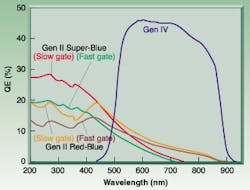
Super Gen II devices use modified photocathode coatings to extend the wavelength range toward the near-IR for military uses or the blue-green for scientific applications (see Fig. 2). The "super blue" Gen II devices have coatings over a fused silica or quartz windows, allowing coverage deep into the ultraviolet (UV) band.Gen III devices were the first to use GaAs coatings for the photocathode. The MCP channels are high resolution (6 µm instead of the 12 µm common with Gen II devices). Sensitivities are as low as 10-5 lux—the illumination under a heavily overcast night sky. Some of these ICCDs are labeled "ultra-blue" because of enhanced blue sensitivity. They use aluminum doping to extend the sensitivity of GaAs coatings.
Current-generation intensifiers, Gen IV, which were introduced in 1999, eliminate the ion-barrier film and yield much higher quantum efficiency in most of the visible and near-IR regions. According to Roper engineers, this is accomplished by greatly reducing the amount of absorbed gases in the outer layers of the glass substrate of the MCP. These gases, mainly hydrogen and oxygen, are converted into the ions that damage the photocathode.
Two techniques are used to eliminate these gases during manufacture—baking in a vacuum at high temperature and scrubbing with an electron beam. Together these lead to more than a hundred-fold reduction of gases in the outer 100 nm of the glass and allow long-life devices without the ion barrier film.1
Gating the pulse
Conventional CCDs tend to be slow reacting, with poor temporal resolution. The image intensifier in an ICCD, though, can be turned on and off—gated—rapidly to produce the required resolution. Gating is achieved by switching the bias applied to the photocathode on or off. If the photocathode is negatively biased, electrons will flow into the MCP. With a positive bias, no electrons will flow.
Since the photocathode material has high resistance, gating times are limited to about 25 ns. To speed up response, scientists deposit a nickel underlay on the cathode to reduce resistance and allow gating items as low as 2 ns. The tradeoff is that sensitivity of the device drops by as much as 40%.
While the gating ratio—the ratio of on to off multiplications—is around 107:1 in the visible region, it falls to 104:1 in the UV region. This is because UV photons can release electrons at the MCP face. To deal with this problem, Roper engineers developed a bracket pulsing technique. Here, both the MCP and the photocathode are biased off, which prevents any multiplication of electrons during the off period. Since the MCP requires some 500 ns to turn on or off, the MCP gating pulse is initiated before the photocathode pulse, so that the MCP on period brackets the on period of the photocathode. This technique requires that timing pulses alert the device to the subsequent arrival of the laser pulse.
As an alternative, a high-voltage pulse can be applied directly to the MCP to produce gating speeds near 10 ns and eliminate any nickel coating that could reduce efficiency. In general, it is only possible to apply the fast, high-voltage pulse to the MCP or the photocathode, not both, because the fast-pulse generators take up too much space to be duplicated.
ICCD applications
Other than military and surveillance- related night-vision applications, ICCDs are primarily used in laser-based scientific measurements. For example, in laser-induced, breakdown spectroscopy, a short laser pulse focused on the surface of a sample creates a plume of highly excited ions. Light from this plume is broken up by a spectrograph and focused onto an ICCD. The ability of the ICCD to gate its response to a few nanoseconds is critical. Since the plume's atomic spectra only becomes distinguishable when the plume has cooled for several milliseconds, repeated short exposures are essential for good resolution and measurement.
Such instruments are now common in the analysis of ore samples and environmental pollutants, as well as the detection of lead in paint samples. These measurements, which usually must be done in the field, require compact, rugged instrumentation.
Several other scientific applications involve the use of laser fluorescence. Laser light can cause flames in furnaces or automotive engines to fluoresce, producing a "signal" detectable with an ICCD. Spectral analysis combined with the imaging capabilities of the ICCD can provide rapid measurements of reactant concentrations and temperature.
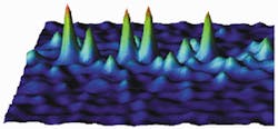
One of the more exotic ICCD applications is single-molecule fluorescence imaging, which is a thrust of ongoing research in the William Moerner Lab at Stanford University. In this technique, background radiation is minimized to isolate the response of a single molecule attached to a substrate such as glass. One approach uses the evanescent near-field wave that occurs when a laser beam bounces off a surface through total internal reflection. The wave, exponentially dropping with distance, extends only 100 to 400 nm, thus reducing any background noise. The sensitivity and response time of ICCDs make them ideal for this type of imaging (see Fig. 3).Intensified CCDs also find use in a variety of other applications. In space, these detectors have been used in such instruments as the far-UV Wideband Imaging Camera of the IMAGE spacecraft, which provides global maps of aurora.2 As ICCD capabilities continue to increase, these detectors will likely find use in even more scientific applications.
REFERENCES
- E. J. Bender, SPIE Proc. 3749, 713 (December 1999).
- S. B. Mende et al., Space Science Rev. 91, 271 (January 2000).
About the Author
Eric J. Lerner
Contributing Editor, Laser Focus World
Eric J. Lerner is a contributing editor for Laser Focus World.


