OTDRs increase in range
Peter Schweiger
The evolution of the optical time-domain reflectometer (OTDR) over two decades has resulted in an instrument with lower noise, higher sensitivity, and wider range.Fusion-splice technology is constantly improving. With the affordability of this essential technology multiplied by the number of splices in today's cable, the capabilities of fusion-splice technology present an enormous challenge to users and manufacturers of optical time-domain reflectometers (OTDRs). Leading-edge techniques are now being used to improve OTDR measurements, meeting the challenge of documenting these small losses. Ways have been developed to handle these almost imperceptible events quickly in a multifiber world.
Portable fusion-splice technology is improving to the point that an operator with a minimum of training can easily produce splices that have an average loss of 0.02 dB or better, using state-of-the-art fusion splicers based on core-alignment methods. Even inexpensive fusion splicers (around $10,000) that use a simpler V-groove (cladding-referenced) alignment method show losses of less than 0.04 dB. The process is simple: after stripping, cleaning, and cleaving the fibers, they are set 1 to 3 mm apart and, at the touch of a single button, the predicted loss is calculated and displayed.
Splices with such low loss values are difficult to see on a standard OTDR trace. Making fiber documentation and fault location clear is a challenge. Improvements in OTDR technology are necessary not only to measure longer links, but also to detect and document these small events.
How to make a better OTDR
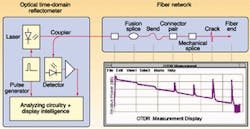
Three improvements in technology can help findor at least documentthe perfect splice. They include better OTDR measurement technology, the use of information from adjacent fibers in a cable, and the application of information on splice positions across all fibers in a cable. These improvements enable detection of splice losses to 0.02 dB (see Fig. 1).
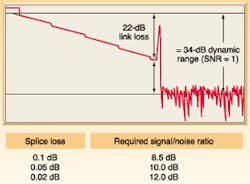
A good signal-to-noise ratio is required in an OTDR measurement in order to see a splice against normal noise that appears in an OTDR trace acquisition (see Fig. 2). The backscatter signal reduces with distance, approaching the receiver noise. In addition, linear and nonlinear optical effects such as Raman scattering within the fiber and the receiver of the OTDR can cause splice signals to be buried in the noise.
The basic layout of an OTDR is fairly straightforward. Improvements have been made to every area of the instrument during the last 20 years, with the result that small splices can be detected farther from the OTDR. The lasers have rapidly increased in power, with selected versions that can produce peak powers of nearly 150 mW. This power is in pulse form with the duty cycle kept low enough to meet strict laser-safety requirements. The increased peak power has a direct effect on available dynamic range, and therefore the available signal-to-noise ratio of any measurement is increased.
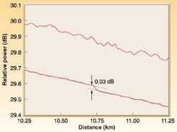
At the other end of the process is the OTDR detector. Like any photodetector, it suffers from thermal and shot noise. To achieve the highest dynamic range possible, this noise must be reduced. Such a reduction can be accomplished through averaging signals togetherwhich takes precious time. An alternative is to select the best components available and to strictly control the environment within the module, thus lowering the noise floor. This approach can result in an OTDR with such a high sensitivity that it can detect the faint energy of tens of thousands of individual photons over a short period of time (see Fig. 3). Beyond the effects of laser power and noise is the response of the optical detection path of both the coupler and the detector to the incoming signal. Certain characteristics of the signal produce a ripple response in the acquisition trace, regardless of signal-to-noise ratio. Optical filtering is needed to reduce these effects.
Getting it right on every fiber
Splice losses can vary; some fusion splices are virtually perfect, showing no measurable loss. In these instances, more sophisticated devices are required. State-of-the-art OTDRs and analysis software allow these "invisible" events to be added by locating a cursor at the expected position, or copying this position from a visible splice at the same position on an adjacent fiber of similar type in the common cable. This "add event" feature allows users to ensure that a template trace can be made that indicates events in every position where one is expected, whether visible or not. This is important when comparing a trace to a route map, and is especially useful during emergency restoration when the relative distance from a break to a landmark such as a splice box is the key to accurate fault location. After all, it is easier to locate a problem 248 m from the fifth splice box than 78.5 km from the beginning of the fiber.
Once a template is made by adding events, advanced OTDRs can lock the event table, forcing measurements at those positions noted in the table on all subsequent fibers measured in that cable. This means that events only have to be added once per position. This feature is an enormous help when measuring hundreds of fibers. If data are already taken and all events are not recorded, methods exist in the best trace-analysis software to add these events and scan the trace at all known splice positions. By making use of one good trace as a templatea function known as "process multiple traces"users can both rescan and add measurements determined by the good trace on every fiber in a project, directory, or simply through selected traces. In combination with the best OTDR hardware, good trace-analysis software can help users to see farther down an optical fiber and enable them to find and document even close-to-perfect splices.
PETER SCHWEIGER is global channel manager at the optical-network test division of Agilent Technologies Canada Inc., 2660 Matheson Blvd. E., Mississauga, Ontario, L4W 5M2 Canada; e-mail: [email protected].


