APDs fit demanding aerospace applications
The latest improvements in high-performance avalanche photodiodes (APDs) have enabled impressive applications in aerospace technology. Avalanche photodiodes have gained acceptance in the aerospace industry because of their very high sensitivity in detecting very low light levels—even down to a single photon. Low noise levels and high signal-to-noise ratio properties also provide benefits in aerospace applications.
Avalanche photodiodes have a built-in gain characteristic that provides a significant advantage in detecting lower light signals. Early APD technology led scientists to develop the single-photon counting module (SPCM), a device that can detect a single photon (see Fig. 1). If there are just two photons present, for example, the SPCM can still detect and differentiate a single photon with as much as 70% accuracy.
The significance of single-photon detection becomes more apparent when applied to an event, such as measuring atmospheric conditions. To examine cloud formations, for instance, a laser beam is transmitted to the cloud and a return signal provides important distance and spectral information. The reflection contains very low light levels and is severely scattered. The few photons of light that actually reflect back can still be detected by the SPCM to accumulate the data necessary for accurate measurement.
APD applications
Common applications include laser range finders that incorporate APD detectors for more sensitive measurements. Avalanche photodiodes used in these applications can operate with lower light levels and shorter laser pulses, resulting in more eye-safe range finders.
Fast receiver modules, confocal microscopy, and particle detection are other common uses for APDs. A silicon APD can detect alpha particles, electrons with energies as high as 150 KeV, and other forms of radiation. Avalanche photodiodes also can be used for light detection and ranging (LIDAR) to measure distance, speed, rotation, and composition of a remote target that can be a clearly defined object, such as a vehicle, or a diffuse object, such as a smoke plume or clouds.
High-performance APDs can be tailored to meet these applications and have proven to be valuable tools in aerospace technology. Selecting the proper photodetector and amplifier circuitry to optimize gain for particular applications has played a major role in evaluating overall system performance (see "Optimizing APD gain," p. 119).
GLAS project
The Geoscience Laser Altimeter System (GLAS) is part of NASA's Earth Science Enterprise (ESE), which includes a series of satellites for measuring Earth's atmosphere, oceans, land, ice, and biosphere for the next 10 to 15 years. GLAS was successfully launched Jan. 12 aboard the Ice, Cloud, and Land Elevation Satellite (ICESat) into a near-polar orbit.
GLAS is the first atmospheric backscatter LIDAR to make continuous measurements of Earth's atmosphere from space. The LIDAR will provide unprecedented views of atmospheric cloud and aerosol structure and provide information on the height and thickness of radiatively important cloud layers for accurate short-term climate and weather prediction.
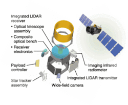
FIGURE 2. One objective of the GLAS instrument (left) aboard ICESat (right) is to measure atmospheric cloud and aerosol profiles from LIDAR return signals at 532 nm. These signals are extremely weak and so the SPCM with silicon APD and active quenching circuits is used because of its high photon detection efficiency (up to 70% at 532 nm) and relatively low bias voltage requirement compared to photomultiplier tubes. These modules were operated in gating mode at low replication rate (40 Hz with 7% duty cycle) and the SPCM was able to reach a wide dynamic range of above 20 mega counts per second. An additional requirement was the ability of the detector to survive intense light reflection. The SPCM module was able to sustain light-pulse intensities of several orders of magnitude above saturation level.
The GLAS system includes a laser to measure distance, a global-positioning-system (GPS) receiver, and a star-tracker attitude-determination system. The laser transmits short pulses (4 ns) of infrared light (1064 nm) and green light (532 nm). Laser pulses at 40 times per second will illuminate spots, or footprints, 70 m in diameter, spaced at 170-m intervals along Earth's surface. Photons reflected back to the spacecraft from the surface of Earth and from the atmosphere, including the insides of clouds, will be collected in a 1-m diameter telescope (see Fig. 2).
CALIPSO project
The Cloud-Aerosol LIDAR and Infrared Pathfinder Satellite Observatons (CALIPSO) project was selected as an Earth System Science Pathfinder (ESSP) satellite mission in 1998 to address the role of clouds and aerosols in Earth's radiation budget. NASA's Langley Research Center is leading the mission and is providing overall project management, systems engineering, payload mission operations, data validation, processing, and archival.
CALIPSO is being developed through collaboration between NASA and the French agency, Centre National d'Etudes Spatiales (CNES), which is providing a PROTEUS spacecraft, the imaging infrared radiometer (IIR), payload-to-spacecraft integration, and spacecraft mission operations. CALIPSO will fly three-channel LIDAR and passive instruments to provide key measurements of aerosol and cloud properties needed to improve climate predictions. Avalanche photodiodes are part of the project: a two-wavelength (532 and 1064 nm) polarization-sensitive LIDAR that provides high-resolution vertical profiles of aerosols and clouds.
CALIPSO has three receiver channels: one measuring the 1064-nm backscattered intensity, and two channels measuring orthogonally polarized components (parallel and perpendicular to the polarization plane of the transmitted beam) of the 532-nm backscattered signal. The receiver telescope is 1 m in diameter.
MOLA science investigation
The Mars Orbiter Laser Altimeter (MOLA) is currently in orbit around Mars on the Mars Global Surveyor (MGS) spacecraft. By transmitting infrared laser pulses toward Mars and measuring their time of flight to determine the range, this instrument constructs a precise topographical map of Mars.
The data has many applications to studies in geophysics, geology, and atmospheric circulation. A telescope focuses the light scattered by terrain or clouds onto a silicon APD, which outputs a voltage proportional to the rate of returning photons that have been backscattered from Mars' surface or atmosphere.
SILEX system
In 1991, a large European consortium began the development phase of an optical communication system known as the Semiconductor Inter Satellite Link Experiment (SILEX) system. This system comprises two optical terminals: PASTEL on board the French satellite, SPOT-4, and OPALE on board the European communications satellite, Artemis, launched in 2001.
The mission of SILEX is to perform satellite-to-satellite optical-communication-link experiments in orbit, transmitting SPOT-4 imagery to Artemis for relay to ground facilities in Europe via its Ka-band payload. High-performance APDs are used as the communication detectors aboard the SILEX terminal.
The SILEX system proves the space qualifications of new technologies and operational procedures, along with demonstrating the software used in both the ground and space segments. It also shows the usefulness of data-relay payloads.
CLAUDE TROTTIER is an engineer, NORBERT BURGGRAF is product leader, and FRANÇOIS BOUCHER is applications engineering leader at PerkinElmer Optoelectronics, 22001 Dumberry Road, Vaudreuil, Quebec, Canada; e-mail: [email protected].
Where Ro is detector responsivity (M = 1); Psig is signal optical power; Popt is optical power (sum of the signal and background power); M is APD gain; F(x) is excess noise factor [F(x) can be approximated by F(x) ª Mx where x is approximately equal to 0.3 for a silicon APD and 0.7 for an InGaAs APD]; Rf is feedback resistor; IB is APD bulk dark current; q is 1.6E-19 coulombs; T is temperature in Kelvin; K is Boltzman constant (1.38E-23 J/K); FET NOISE is average spectral noise from the input GaAs FET (this expression is utilized to simplify the SNR equation as this noise component is frequency dependent; one must integrate the FET noise to obtain the exact noise contribution); Igs is FET gate leakage current; ILS is detector surface-leakage current (unmultiplied component); NEB is noise bandwidth (1.57 * signal BW for a first-order rolloff).
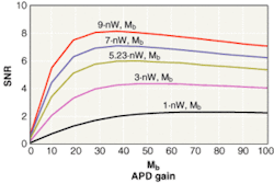
The equation shows that once the APD noise becomes dominant, increasing the gain will eventually degrade the SNR figure. To determine the optimum gain for a specific application, a family of curves must be generated showing the SNR vs. APD gain for several optical powers (see figure). In the figure, a target SNR of 6 was imposed on the receiver. Each curve is drawn for a fixed optical power and shows the SNR variation as the gain is ramped from 1 to 100. The maximum of the curve corresponds to the optimum APD gain for this optical power.
To determine the receiver sensitivity for a specific SNR, one must identify the smallest optical power that will meet this SNR requirement (6 in this example). The maximum point for this optical power will correspond to the optimum gain. Using a smaller or larger APD gain would reduce the receiver sensitivity.
FB


