Negative photoconductance boosts APD frequency response
With their high internal current gains, avalanche photodiodes (APDs) are used for high-speed optical detection in satellite, long-haul, and free-space telecommunications—all of which require the sensing of extremely weak light signals modulated in the Gbit/s range. Ordinary APDs are limited in frequency response (speed) by the very avalanche buildup that enables them to sense faint signals. Researchers at the Electronics and Telecommunications Research Institute (ETRI; Taejon, Korea) have exploited a phenomenon called negative photoconductance to eliminate the speed limit imposed by avalanche current gain.1
Known as negative differential resistance in electronic devices, negative photoconductance in an APD shows itself as a negatively sloped net photocurrent (the difference between the illuminated current and the dark current) in the avalanche region. The researchers attribute the negative photoconductance to field-induced transfer of electrons from the conduction-band minimum to more-energetic low-mobility valleys. As a result of increased carrier speed and concentration, the current increases even though electrons end up in low-mobility states.
The researchers constructed several APDs with mesas ranging in size from 5 to 50 µm. The indium aluminum gallium arsenide/indium aluminum arsenide devices were grown by metalorganic chemical vapor-phase epitaxy or molecular-beam epitaxy on indium phosphide substrates. A resonant-cavity structure boosted the optical field within the detector. For test, light was brought to the APDs with a fiberoptic probe.
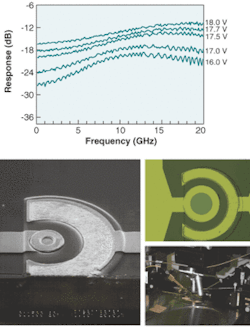
The smaller devices show a higher 3 dB with less current gain, while the larger devices have a higher current gain (up to 30) with a lower 3-dB bandwidth. A 12.5-µm device has a frequency response that decreases by 3 dB at 40 GHz, while a 5-µm device shows a response that increases all the way up to 20 GHz, and also increases with more bias (see figure).
Tests with 700-fs pulses from a 1.55-µm-emitting fiber laser show a high-speed (on the order of 100 ps) response signal that forms at the threshold voltage in the avalanche region. According to Gyungock Kim, a principal researcher at ETRI, on-wafer measurements of the devices show good open eye diagrams at high gains at 20 and 40 Gbit/s, despite the large connection loss of the measurement setup.
REFERENCE
- Gyungock Kim et al., Appl. Physics Lett. 8(6)(August 11, 2003).
