Push the right button to boost camera performance
Push the right button to boost camera performance
You must understand how to optimize operating parameters of CCD cameras to obtain high-quality images from various applications.
Lisa Merrill and Alan Lichty
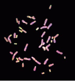
High-performance charge-coupled-device (CCD) cameras are being used in a growing range of applications--from genetic research to semiconductor testing, from precise motion analysis to three-dimensional microscopy. Not surprisingly, the commercial CCD camera systems that support these applications offer an increasing level of flexibility, allowing them to be precisely optimized for a wide range of operating conditions. Much of this utility has been achieved through the use of powerful system software that allows even novice users to easily set camera parameters as well as to create complex image acquisition and analysis routines (see photo).
The influence of several significant camera parameters and how the imaging system operation can be optimized to yield dramatic improvements in data is discussed here.
CCD camera operation
A brief review of how a CCD camera image is recorded will hel¥in understanding imaging-system optimization. [For more details, see Laser Focus World, Dec. 1994, p. 53--Ed.] The CCD imaging array itself has no inherent gain. Every incoming photon generates a single free electron in the pixel it impacts, with a probability ranging from 0% to 70%. This probability is known as the quantum efficiency and is wavelength-dependent, loosely following the absorption curve of silicon. The number of electrons is determined by the light level in the image and the exposure (integration) time.
There will also be a few "rogue" background electrons found in each pixel, known as dark electrons. The number of these dark electrons is strongly dependent on the CCD operating temperature. The correspondence between object "pixels" and CCD pixels is determined by the magnification of the optical system being used.
The array of active pixels is referred to as the parallel register. Prior to readout, the inherent signal-to-noise ratio (S/N) of the image stored in these pixels is determined by the shot noise--the natural statistical variation in the number of photons arriving at each pixel. Shot noise is the statistical variation in the light-absorption process.
Each exposure results in an array of captured charges in the form of a two-dimensional matrix. This n ¥ m matrix is transferred, row by row, into the serial register. The individual pixels in the serial register are then transferred in serial fashion into an output node. Camera electronics measure the charge in this node, digitize the charge, and clear the node of electrons, leaving it ready for the next serial transfer. This readout process introduces statistical variations known as read noise. The readout speed is usually limited by the speed of the camera analog-to-digital (A/D) converter, with a maximum of several megahert¥(millions of pixels/second).
A process known as binning allows the charge from several pixels to be combined before readout. This reduces the number of individual readout events and thus decreases the total readout time, allowing the user to set the camera to a faster frame rate. Binning is possible in both the x and y directions, either by combining multiple rows into the serial register before undergoing serial transfer or by reading multiple serial pixels into the output node between individual readouts. Because it increases the S/N, binning is also used for low-light applications. The trade-off for higher frame rate and increased S/N is reduced spatial resolution.
The preamplifier and A/D converter both have an associated gain value. The A/D setting is referred to as the system gain and is factory set. This is the relationshi¥between number of electrons and number of ADUs (analog-to-digital units) and is usually set to match the maximum number of electrons that can be accurately captured in a single pixel (the full-well capacity). For example, a 12-bit camera would have 212 (4096) ADUs; if the full-well capacity of the CCD is 50,000 electrons, then there are 12.2 electrons/ADU. The preamplifier gain is known as the user gain and can be set by the operator through software commands. The user gain amplifies the measured charge by a factor (usually 1, 4, or 8) before digitizing, and it thus increases the intensity resolution of the camera.
Once each image is stored, it can be manipulated in various ways by the system software. One of the most important of these is flat-field correction, which allows images to be corrected for response nonuniformities, either from inherent illumination variations in the image or because of anomalous pixel response. Images can also be combined, ratioed, and/or subtracted in various ways.
When it comes to displaying images, the typical dynamic range of the digitizer (usually 12, 14, or 16 bits) is many times greater than the gray scale of the monitor or printer being used for output and the eye (6 bits). Stored digital values are converted to the lower gray scale using look-u¥tables (LUTs). These can be simple linear relationships or values set u¥to enhance or expand a part of the camera`s gray scale. False color can also be introduced to enhance the displayed image.
Applications
The simplest way to understand the importance of major camera variables (see box on p. 124) is to take a brief look at how a camera might be optimized for three different operating conditions. Low-light level, high-light level, and high-speed operation each present particular demands on the optimization process.
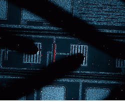
Low light levels. Some of the most demanding applications for CCD cameras involve extremely low light levels. Typical examples include astronomy, Raman spectroscopy, and semiconductor failure analysis (see Fig. 1). In these, the biggest concern is usually reaching an acceptable signal-to-noise ratio. Ideally, S/N would be limited purely by the shot noise of the incoming light.
To achieve this condition, it is necessary to minimize read noise and dark noise (natural statistical variations in the dark count). The two most important user-controlled camera variables for accomplishing this are integration (exposure) time and operating temperature. Binning may also be used if the situation merits combining pixel charge in this manner.
Assuming reasonably constant scene illumination, lengthening the exposure time will linearly increase the signal. However, longer exposure time will also increase the dark current per pixel. Therefore, unless the scene illumination can be increased, the only way to increase the ratio of the signal to the dark current is to actively cool the CCD array.
A typical liquid-nitrogen-cooled camera (at, say, -110°C) produces between one and 12 electrons of dark current per pixel per hour, depending on camera type. By comparison, thermoelectrically cooling the same camera to only -45°C will give a dark current between 6 and 20 electrons/pixel/second. For example, to get a signal-to-dark noise ratio of 10, the camera temperature must be set to a value where the dark current is 1/100 of the typical signal.
Read noise is a constant for most high-performance cameras, independent of integration time. For example, each readout event in a Photometrics camera produces read noise of less than 10 electrons per pixel readout. Generally speaking, exposures that result in signals of 100 electrons/pixel or fewer will be read-noise limited, whereas images with more than 100 electrons/pixel will be shot-noise limited.
Thus, to minimize read noise, it is preferable to have one long exposure rather than averaging several images of shorter exposure time. Unfortunately, this may be unavoidable in very-low-light conditions or where exposure times cannot be sufficiently lengthened. To circumvent this problem, on-chi¥binning can be used to combine the accumulated electrons from several pixels into fewer "superpixels." Binning increases the signal while the read noise remains constant. Because this is performed before readout, the ratio of signal to read noise is increased by N, where N is the number of pixels in each superpixel. Spatial resolution, however, is lowered by binning.
The contrast with which these images are recorded can be enhanced under some circumstances by setting the user gain to its maximum value (usually 4X). To display these data with maximum contrast will require selecting a LUT that maps the low-intensity range of the camera onto the full-intensity range of the display device, which can be a CRT or printer.
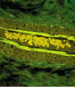
High light levels. High-light-level applications are usually straightforward, except when you are trying to measure small intensity variations against a bright background. Examples of this include solar observations, film digitization, and bright-field microscopy (see Fig. 2). These applications rely on the large dynamic range of the camera system. They require a CCD array with a large full-well capacity (maximum electrons/pixel). These factors should be considered before buying a camera for such an application.
Neither read noise nor dark noise plays any role for these applications, as the data are shot-noise limited. Measuring a small signal against the shot noise of a large background often requires long integration times. For a constant (steady-state) image, the signal increases proportionally to time, whereas the noise increases according to the square root of time.
Obviously the integrated signal level will be high under these conditions, hence the need to use a CCD chi¥with a large full-well capacity, such as the SI502A from SITe (Beaverton, OR). This chi¥has a full-well capacity of 330,000 electrons. To avoid saturating or overloading the pixels, a user gain of 1X should be used. At this setting, the digitizer is matched to the full-well capacity of the CCD.
To best display or print these images you should choose a nonlinear LUT that expands the to¥end of the camera`s ADU scale. For general high-light-level applications, it may be better to use multiple short exposures rather than one long exposure. Spurious data points caused by cosmic events (high energy particles) can be removed from individual frames before averaging them all, or certain frames can be discarded altogether.
High-speed applications. Although initially developed for low-light staring applications such as astronomy, high-performance, cooled CCD cameras are increasingly being used in applications needing high frame rates (see Fig. 3). Many of these are in the biological sciences, most notably calcium ratio imaging--fluorescence monitoring of local calcium-ion concentrations while neurons and other nerve cells are stimulated in various ways. Many of these applications require imaging events that may change in a few tens of milliseconds or even faster.
High-end scientific cameras have variable readout rates that can be set as high as several megahertz. Even running at 2 MHz, a typical 512 ¥ 512 array can thus be operated at a theoretical maximum of eight frames/second. In practice, this to¥speed will be even slower because of the time overhead for image acquisition and exposure, shutter opening and closing, and the parallel and serial transfers of charge.
Fortunately, binning allows the frame rate to be increased at the expense of spatial resolution. To a simple first approximation, 2 ¥ 2 binning (4 pixels to 1 macropixel) potentially increases the frame rate by a factor of four. However, the time overhead for transfers and the mechanical limitations of the camera shutter have not allowed these cameras to exceed frame rates of about 25-30 frames/second.
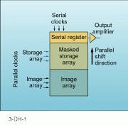
This situation is changing, though, as camera manufacturers start to offer products designed specifically for higher-speed applications by using frame-transfer CCD arrays such as the Photometrics PXL37. The parallel pixel register in these devices is split (usually 50/50) into a normal imaging array and a blind (masked) storage array. A captured image can be rapidly shifted to the storage array on a 1-2-ms time scale. Another exposure can be immediately commenced while the stored image is sequentially transferred and read out (see Fig. 4).
Being able to run the acquisition and readout processes simultaneously cuts the total time overhead for the experiment. In addition, the fast transfer between the two arrays allows shutter-free operation for most applications, which frees the camera to run at rates as high as 120 frames/second using appropriate binning.
Modern CCD camera systems provide powerful, flexible imaging solutions for a wide variety of applications. Furthermore, this functionality is becoming increasingly accessible through the use of object-oriented, menu-driven software. As with any instrument, however, optimum performance can be achieved only by understanding the trade-offs that occur between various system parameters. n
ACKNOWLEDGMENT
The article draws on material from our company`s Performance Imaging Workshop, an intensive short course created by Paula Harcarik, Alan Lichty, Lisa Merrill, Carey Portnoy, and Scott Sternberg. (The course will be offered in May 1995 in Tucson, AZ. For more information contact Lisa Merrill at (602) 889-9933.)
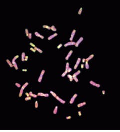
CGHu27-4 is a comparative genomic hybridization of green-labeled DNA from a primary prostate tumor and red-labeled normal male DNA (metaphase chromosomes). The red regions of the chromosome are indicative of deleted regions in the tumor, and the green regions represent possible amplifications of regions in the tumor.
FIGURE 1. Only low light levels are available when inspecting emission sites on an integrated circuit chi¥with a CCD camera.
FIGURE 2. High light levels are needed when using a CCD camera to examine a diseased tissue section.
FIGURE 3. Visual cortex of a monkey shows response to visual stimuli. Activity was imaged at 50 frames per second.
FIGURE 4. In bioimaging and other fast applications, a frame-transfer array provides high frame rates from CCD cameras such as the Photometrics PXL37.
