Select the photomultiplier tube that matches your application
Since the first commercial photomultiplier tube (PMT) was developed in the early 1940s, it has remained the detector of choice in instruments that require low noise and high sensitivity. The PMT is firmly entrenched in many fields, from analytical chemistry to medical imaging, industrial process control, and high-energy physics. Now, as always, understanding the way the devices work and their key specifications is extremely helpful in matching a PMT to a specific application.
Basic PMT operation
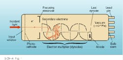
Photomultiplier tubes are vacuum tubes that consist of a glass, ceramic, or metal envelope, a photoemissive material (photocathode), secondary emitting electrodes (dynodes), and a collection electrode (anode, see Fig. 1). A photon passing through the PMT window is absorbed by the photocathode if the energy of the photon exceeds the binding energy of the photocathode material. An electron is released in accordance with the photoelectric effect, which was described by Einstein early in this century (see Laser Focus World, Oct. 1994, p. 93).
If the electron has sufficient energy, it will escape into the vacuum of the tube. Once there, it will be accelerated toward the first dynode by the potential difference between the photocathode and first dynode. A collision will result, and the energy of the primary electron will produce a number of secondary electrons. These are in turn accelerated toward the second dynode, where additional electrons are created. This process repeats until finally a cloud of electrons, composed of more than one million electrons, is collected by the anode and read out as the signal.
Photocathode importance
Choosing the correct photocathode is probably the most important aspect of matching a PMT with its intended application. The purpose of the photocathode is to convert light into electrons, and the efficiency with which it does so determines whether or not the PMT is useful for a specific application.
The quantity of light falling on a PMT can be defined in three ways. It can be expressed as a number of photons at a specific wavelength (such as 100 photons/s at 800 nm). It can be given as the radiant power incident on the tube at a specific wavelength (40 pW at 400 nm). Or it can be expressed as the amount of luminous flux falling on the PMT (10 microlumens). The photocathode sensitivity can be expressed in these ways as well.
Quantum efficiency (QE) is the ratio of photons incident on the PMT to electrons emitted from the photocathode. The QE is usually expressed as a percentage at a specific wavelength. So if 100 photons are incident on a PMT and its QE is 50%, then 50 electrons will be produced by the photocathode. The QE shows the intrinsic sensitivity of a PMT to light.
Radiant sensitivity is the amount of electrical current that is produced by a given amount of radiant flux and is described in units of amperes/watt (A/W) at a specific wavelength. For example, if 40 pW is incident on a PMT with 0.1 A/W radiant sensitivity, the photocathode will produce 4 pA of current. Luminous sensitivity is the amount of electrical current produced by a given amount of luminous flux. Because this is a photo-optic measurement, it corresponds closely to the human eye. So 10 microlumens of flux incident on a PMT with sensitivity of 100 µA/lumen will produce 1 nA of current.
Spectral response is a term used by optoelectronics manufacturers to state the "useful" spectral range over which a device will operate. This parameter is helpful in choosing the appropriate PMT for an application operating over a particular wavelength range. Spectral response, however, does not take into account radiant sensitivity. Consequently, spectral response should be used as a starting point in choosing a PMT, but radiant sensitivity should ultimately determine which tube is best.
Two primary photocathode configurations are used in PMTs. The opaque or reflective type is generally used in side-on PMTs and the semitransparent or transmission type is typically used in head-on tubes. Opaque photocathodes generally have higher UV and IR sensitivity, while semitransparent photocathodes perform better in the blue and green regions of the spectrum (see Fig. 2). Optical coupling is usually better with semitransparent photocathodes.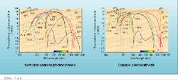
Applications requiring wide spectral response, such as spectroscopy, generally use side-on tubes in the instruments. However, applications such as scintillation counting that require very efficient optical coupling and high QE in the blue region use semitransparent photocathodes.
Dynodes—multiplication stages
A unique feature of a PMT is its ability to amplify the very weak signals produced by the photocathode to levels suitable for use by data-acquisition systems without introducing significant amounts of noise. The dynodes are responsible for producing the amplification, or gain, in a PMT. Gain is also important when the PMT is used with noisy amplifiers because it can improve instrument performance by raising the desired signal level above the noise.
When considering how much gain is necessary in a PMT, simply multiplying the photocathode sensitivity by the gain will give the anode sensitivity or the total tube sensitivity. Using the examples given above for radiant sensitivity, 40 pW would be amplified to produce an anode current of 4 µA; this is a very usable signal.
In addition to gain, the dynodes also determine other characteristics of the PMT. For instance, speed of response, linearity, resistance to magnetic fields, and uniformity of response are all in part determined by the selection of the dynode (see Fig. 3).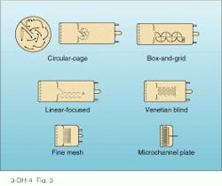
Response speed
Two basic properties—the design of the electron optics and the strength of the electric field between electrodes—determine the response speed of a PMT. Three properties describe timing performance. Risetime is the time required for the PMT output to rise from 10% to 90% of peak amplitude when the entire photocathode is illuminated by a light pulse of less than 50 ps.
Electron transit time is the time between the arrival of a pulse with a width of 50 ps or less and the instant when the anode output reaches its peak value. Transit-time spread is the jitter or spread in the electron transit time and is usually specified at full-width-half-maximum (FWHM) of a histogram of the electron transit time.
Very good PMT timing properties are required in many applications, including fluorescence-lifetime measurement, time-of-flight counters for high-energy physics, and lidar (light detection and ranging). In any application in which timing is a priority, care should be taken to select a tube with high sensitivity as well as good timing characteristics.
Dark current
In an ideal PMT, the only signal produced by the photocathode would be current generated by light incident on the tube. In reality, the PMT produces current whether there is light present or not. Cathode signals produced in the absence of light are known as dark current and are produced thermally by the photocathode. In other words, electrons are excited into the vacuum in the tube by thermal excitation and not by photons. More dark current is produced by tubes with longer spectral responses because of the lower binding energy of red-sensitive photocathodes. In addition to cathode thermal emission, leakage currents play a role in dark-current production when operating at low gain.
Dark current is of concern to instrument designers because the noise it produces determines the minimum light power that can be detected. Any application in which very low light levels can be detected should use PMTs with low dark current. The alternative is to cool the tube to reduce the dark current; this step is effective because most dark current is produced thermally.
Making the choice
While all designers would like to treat the detectors in their instruments as black boxes (light in, signal out), this is rarely the case. Like all detectors, PMTs are complex devices, so choosing the right one for a particular application involves detailed analysis.
High sensitivity should be at the top of any list, followed by dark current, and finally by application-specific requirements such as high speed. The high sensitivity and low noise of a PMT ensure that the venerable device will be a viable detector solution for many years to come.
About the Author
Earl Hergert
VP of Marketing, Hamamatsu
Earl Hergert is VP of Marketing at Hamamatsu (Bridgewater, NJ).