How to select avalanche photodiodes
SERGE MELLE and ANDREW MACGREGOR
Optical measurement plays an important role in a variety of scientific, medical, and industrial applications. Simple optical systems use inexpensive photocells for light detection, but many applications require higher accuracy or enhanced sensitivity. Traditionally, high sensitivity has been obtained using photomultiplier tubes (PMTs). However, the photon-level sensitivity of PMTs comes at the expense of price, fragility, sensitivity to magnetic fields, size, and high-voltage power-supply requirements.
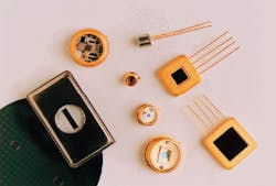
By contrast, semiconductor detectors offer small size, ruggedness, and ease of use. Manufactured using proven wafer-scale silicon or III-V batch-processing techniques, they are inherently cheaper and provide better than 70% quantum efficiency beyond 400 nm. The workhorse semiconductor detector is the PIN photodiode. In some applications, however, PIN photodiodes cannot match the sensitivity of PMTs, and avalanche photodiodes (APDs) should be considered. The high sensitivity of APDs rivals that of PMTs, leading to their use in a variety of applications including blood analysis, laser rangefinding, fiberoptic communications, barcode scanners, single-photon counting, and particle detection (see photo).
What is an avalanche photodiode?
An APD differs from a PIN photodiode by providing internal signal gain. Output signal current, IS, from an APD is
IS = Ro MPS, where Ro (amps/watt) is the intrinsic responsivity of the APD, M is the gain, and PS (watts) is the incident optical power. The internal gain of an APD is dependent upon the APD reverse voltage, VR, and provides greater detection sensitivity than a PIN receiver when the latter`s sensitivity is limited by preamplifier noise (see Fig. 1).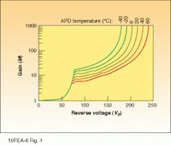
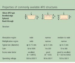
To understand why more than one APD structure exists, one must consider the trade-offs accommodated by the APD designer. The ideal APD would have zero dark noise, no excess noise, broad spectral and frequency response, a gain range from 1 to 106 or more, and low cost. More simply, an ideal APD would be a good PIN photodiode with gain! In reality, this is difficult to achieve due to the need to trade off conflicting design requirements. Some of these trade-offs and how they are optimized in commercial APDs are discussed below.
Consider the cross section of an APD structure (see Fig. 2). The basic elements provided by the APD designer include an absorption region A, and a multiplication region M. Present across region A is an electric field E1, that separates the photogenerated holes and electrons and sweeps one carrier toward the multiplication region. The doping profile in the multiplication region exhibits a high electric field, E2. This field profile must be high enough and sufficiently broad to provide useful gain by collisional ionization, but must maintain the electric field below the breakdown field of the diode.
Avalanche photodiodes are available spanning a wide spectral range. Silicon APDs are used between 400 and 1100 nm, germanium between 800 and 1550 nm, and indium gallium arsenide (InGaAs) between 900 and 1700 nm. Although more expensive than germanium, InGaAs APDs provide lower noise and higher frequency response for a given active area. Germanium APDs are recommended for applications in which amplifier noise is high or cost is a prime consideration.
Choosing the right detector
APDs are generally recommended for high-bandwidth applications or where internal gain is required to overcome preamplifier noise. The following steps can be used to select the appropriate detector:
- Determine the wavelength range to be covered and select the appropriate detector type.
- Determine the minimum detector size that can be used; effective optics can be cheaper than using an overly large detector.
- Determine the required electrical frequency bandwidth of the system; overspecifying bandwidth will degrade the signal-to-noise ratio (S/N) of the system.
- Perform a S/N calculation for a PIN detector versus an APD (see "Calculating APD spectral noise and excess noise factor") to justify whether an APD is required.
One of the key parameters to consider when selecting an APD is noise performance. Like other detectors, an APD will be operating in one of two noise-limited detection regimes. Sensitivity will be limited by dark-current shot noise or preamp noise at low light levels and by signal shot noise at higher powers. However, APD noise performance is degraded by an excess noise factor, F, and provides a S/N at higher powers that is worse than a PIN detector with the same quantum efficiency. It therefore makes sense to replace a PIN with an avalanche photodiode if preamplifier noise exceeds the quadratic sum of the PIN detector noise and photon shot noise on the signal.
Achievable detector S/N at a specific wavelength and bandwidth should determine the optimum detector type. Figure 3 shows a S/N simulation comparison for a 0.5-mm silicon PIN detector and APD at 830 nm and several system bandwidths. At low frequencies, where detector noise is dominant over amplifier noise, a PIN detector provides higher S/N for power levels greater than 10 pW. At high system bandwidths, preamp noise becomes dominant, thus justifying the use of an APD for higher S/N at low light levels.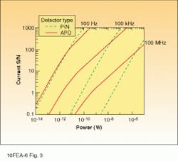
Evident in the curves is the "knee" where S/N becomes limited by signal shot noise.
In selecting an APD, it is important to effectively compare competing manufacturers` specifications. Significant parameters include responsivity, dark current, noise, and temperature coefficient.
Responsivity and gain. For many APDs, it is not practical to make an accurate measurement of intrinsic responsivity, RO, making it inappropriate to state sensitivity at M = 1. Rather, an operating voltage should be specified for a given responsivity. Diode-diode variations lead to a distribution in the operating voltage, and manufacturers should also specify a voltage range within which a specific responsivity will be achieved.
Dark current and noise. Total APD dark current includes surface and bulk leakage currents, the latter being multiplied by APD gain. At M = 1, dark current noise is dominated by surface current, which may contribute significantly less noise than multiplied dark current at operating gain. Therefore, APD dark current and spectral noise should be specified at the operating responsivity or gain.
Temperature coefficient. APD breakdown voltage increases with temperature, and gain is thus temperature-dependent. Usually a few percent per degree Centigrade, this dependence must be specified and compensated for in the bias supply or overall system design.
Operating specifications. The responsivity and dark current of APDs is often specified at a percentage of breakdown voltage (that is, R(l) at VR = 0.9VBR). However, variations in the gain and noise vs. voltage characteristics of a specific APD type, or between competing designs, prevent valid comparison of APD characteristics using this method. This method does not imply measurement at equal gain and only indicates typical characteristics.
APD applications
Laser rangefinding. The most common application of APDs is in rangefinding, either in free space (laser rangefinding or lidar) or within optical fibers with instruments such as optical time-domain reflectometers (OTDRs). Laser rangefinders typically use 905-nm or 1.06-µm pulsed laser transmitters with peak powers from 10 W to kilowatts and pulsewidths (t) between 5 and 100 ns, while OTDRs operate at 1300 or 1550 nm.
An APD/amplifier combination is used to detect the faint return reflections from the target. Receiver bandwidth (B) is typically designed so that B ª 0.35/t. For optimal timing resolution of the return pulse, higher bandwidths within S/N design limits are used. The S/N depends on the collection optics and receiver combination. For optimum S/N, a design/cost compromise must be struck between fast optics (low f-number), detector diameter, and preamp type. Hybrid APD/preamplifier receivers offer up to five times better sensitivity than use of external high-frequency preamps but are more expensive.
The best possible performance is achieved through the use of cooled hybrid APD receivers. Cooling improves noise by reducing bulk dark current, and temperature stabilization eliminates gain variations with temperature. Performance achieved with standard APDs includes detection of 100-photon, 20-ns pulses at 830 nm. At the other end of the spectrum, the expected emergence of low-cost/high-volume APDs is likely to extend their use in recreational rangefinders for golfing or hunting and in automobile collision-avoidance systems. Rangefinding performance in these applications is currently limited by the use of PIN detectors and short pulsewidths mandated by eye-safety requirements.
High-speed receivers. Avalanche photodiodes are used in high-bandwidth receiver modules for fiberoptic communication systems to provide greater S/N compared to a PIN receiver. Typical fiberoptic systems transmit 1310- or 1550-nm light pulses at 622 Mbit/s or 2488 Mbit/s over single-mode fiber and use InGaAs detector-based receivers.
A typical fiberoptic receiver mates a detector and transimpedence amplifier (TIA) to provide a voltage output for interfacing to clock recovery, signal reshaping, and decision circuits. The amplifier circuit typically uses a FET-input hybrid circuit or monolithic TIA integrated circuit. Noise is dominated by the combination of Johnson noise from the low feedback impedance required for extended bandwidth and total input capacitance.
Preamplifier input noise limits PIN receiver sensitivity. To remedy such problems, an APD is therefore used to provide signal gain before the preamp input. The increased S/N permits effective processing of the output by subsequent receiver electronics. Sensitivity can be increased 6 to 8 dB at 2.5 Gbit/s using InGaAs APDs. This increases transmitter-receiver spacing in a typical fiberoptic transmission system by up to 30 km, reducing cost outlays for transmission equipment.
Single-photon counting. Selected avalanche photodiodes can be used in the "Geiger" mode for single-photon-counting applications, where light-flux levels can be as low as tens of photons per second. These include bioluminescence, fluorescence spectroscopy, and astronomy. In Geiger mode, an APD is biased several volts above breakdown voltage for operation at very high gain (typically 105 to 107). When biased above breakdown, an APD normally conducts a large bulk current. However, if limited, there is a probability that the current will fluctuate to zero, and the APD will remain "off" until triggered by a bulk or photogenerated carrier avalanche. The value of the bulk dark current is therefore significant in selecting a photon-counting APD. To date, only selected silicon APDs have dark currents low enough for commercial photon-counting instruments, with record dark counts <1 count/s at -20°C being reported by EG&G Optoelectronics using <0.5-mm-diameter devices. In the laboratory, however, photon counting has also been demonstrated with germanium and InGaAs APDs.1The effectiveness of an APD system for photon counting depends on two important specifications. The first is the photon-detection efficiency of the APD, representing the probability that a photon is detected and then generates an avalanche of sufficient magnitude to trigger a comparator circuit. The second is the system`s recovery time after a detection event during which the APD cannot detect photons, referred to as "dead time."
The two principal ways of configuring an APD circuit for photon counting use either a passive or active quench circuit.2,3 A passive quench circuit uses a load resistor to limit APD current to below the level at which continuous discharge occurs. The RC time constant of the circuit determines the recharge rate, with typical dead times of approximately 300 ns. Maximum count rates of approximately 106 counts/s limit use to applications with low count rates.
For a shorter dead time and higher photon-detection efficiency (up to 60%), an active quench circuit is recommended. By actively forcing the APD reverse voltage below VBR immediately upon initiation of an avalanche pulse, the diode discharges completely before the high voltage is reapplied. Recharging is done rapidly using a low-value load resistor or transistor. A typical active quench circuit lowers dead time to 35-50 ns and is recommended in higher photon-flux applications.
Continued research and development of new APD structures promises to broaden their use in a range of applications. Large-area APDs with active areas up to 100 mm2 are being developed as PMT replacements and for nuclear-particle detection, either directly or using scintillator crystals. Superlattice III-V APDs using quantum-well structures for low-noise and high-gain-bandwidth products are being developed to enhance receiver sensitivity in fiberoptic systems operating at rates of 10 Gbit/s or more. These and other developments will augment the capabilities of optical systems and increase their importance in everyday applications.
REFERENCES
1. S. Cova et al., "Avalanche photodiodes for near-infrared photon-counting," SPIE Proc. 2388 (1995).
2. H. Dautet et al., Appl. Opt. 32(21), 3894 (1993).
3. Product data sheet ED-0017/03/88: C30902E/S, C30921E/S, EG&G Canada Ltd., Vaudreuil, Quebec, Canada.
Calculating APD spectral noise and excess noise factor
Avalanche-photodiode noise is caused by dark current and photocurrent shot noise, (In(SHOT)). This derives from the random fluctuations in current flow. For a PIN detector this is given by
(in(SHOT)) = (2qID, S)1/2
For an APD, bulk leakage current, IDB, is multiplied by the gain. Dark current ID therefore equals
ID = IDS + IDBM
where IDS is the surface dark current.
Total APD spectral noise current in "illuminated" conditions equals the quadratic sum of detector noise and signal shot noise, expressed in amps/Hz1/2. For a given optical signal power, PS, this is given by
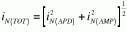

All APDs generate excess noise due to the statistical nature of the avalanche process. The excess noise factor given by F is the factor by which APD shot-noise performance is degraded compared to a PIN detector. The excess noise factor is a function of the carrier-ionization ratio, k, defined as the ratio of hole to electron ionization probabilities (k 1). Excess noise can be calculated using the model developed by McIntyre,1 which considers the statistical nature of avalanche multiplication. The excess noise factor is given by
The k factor, kEFF, can be measured experimentally or calculated theoretically from the carrier-ionization coefficients and the electric-field profile of the APD. Many manufacturers approximate F using an empirical formula, given as
F = MX
where the value of "x" is derived from a log-log plot of F versus M. This approximation is sufficiently good for many applications, particularly for InGaAs or germanium APDs, which have a high k factor. The table provides typical values of k, F, and x for silicon, germanium, and InGaAs APDs.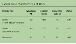
REFERENCE
1. R. J. McIntyre, IEEE Trans. Electron Devices, ED-13, 164 (1966).