Computed tomography adds third dimension to terahertz imaging
By Bradley Ferguson and X.-C. Zhang
Unlike traditional x-ray CT, which only measures the amplitude of the transmitted radiation, t-ray CT measures the transmitted pulse shape to reveal more information about the sample.
Terahertz radiation occupies a large portion of the electromagnetic spectrum between the infrared and microwave bands from 0.1 to 10 THz. This frequency range presents the next frontier in imaging science and technology. Compared to the relatively well-developed imaging techniques at microwave and optical frequencies, however, basic research, new initiatives, and advanced technology developments in the terahertz band are very limited. The "THz gap" is a scientifically rich but technologically limited frequency bandlargely because efficient terahertz emitters and receivers are a relatively recent invention.
For just over a decade terahertz time-domain spectroscopy has been used to determine the optical properties of materials in the submillimeter wavelength regime. More recently, two-dimensional terahertz imaging has been demonstrated for a diverse range of applications including imaging semiconductors, leaf moisture content, flames, skin burn severity and skin cancer.1, 2
Terahertz imaging is attractive for several reasons: the radiation is nonionizing and poses very few safety risks, it is capable of submillimeter resolution and, significantly, several materials, including paper, plastics, and cardboard, are relatively transparent in this frequency band. Conventional terahertz imaging techniques, however, cannot determine the three-dimensional (3-D) structure of objects.
Terahertz computed tomography (t-ray CT) is a new tomographic imaging modality that allows pulsed terahertz radiation to probe the optical properties of 3-D structures.3 It provides sectional images of objects in a manner analogous to conventional computed tomography techniques such as x-ray CT. Terahertz CT systems directly measure the transmitted amplitude and phase of broadband terahertz pulses at multiple projection angles through a target, which allows a wealth of information to be extracted from the target object, including both its 3-D structure and its frequency-dependent far-infrared optical properties. It extends the capabilities of previous t-ray tomography systems by allowing more general 3-D targets to be imaged.4
T-rays image 3-D structures
Terahertz CT draws inspiration from the now ubiquitous x-ray CT system. The hardware is a relatively simple extension of modern transmission-mode terahertz imaging systems. The target sample is mounted on a rotation stage that allows it to be rotated, and a 2-D terahertz image is obtained at each projection angle. The data can then be processed using the filtered backprojection algorithm to reconstruct the refractive index and absorption coefficient at every position within the sample volume.
Terahertz pulses are generated using ultrafast lasers. The laser emits pulses of 800-nm (near-infrared) light that are only 100 fs long. The laser pulses trigger a photocurrent in a gallium arsenide (GaAs) photoconductive antenna that results in the emission of broadband pulses of terahertz radiation. This radiation is then focused and transmitted through the target. After transmission, it is collected using parabolic mirrors and focused onto a zinc telluride (ZnTe) electro-optic (EO) detector crystal.
The data acquisition speed is an important concern in all terahertz imaging systems and it is of particular concern for t-ray CT, in which multiple images of the object must be obtained. Hence, a linearly chirped optical probe beam is used for EO detection of the terahertz pulses.4, 5 Using this technique the full terahertz waveform is measured simultaneously, dramatically accelerating the imaging speed. The target is then raster scanned in x and y dimensions to form a 2-D image.
This technique is still quite time-consuming; a typical image of 100 x 100 pixels measured at 18 projection angles can take more than an hour. Fortunately, there are several methods available to improve this speed. The acquisition time can potentially be reduced to under a minute by using a CCD camera for 2-D terahertz imaging.6
Reconstructing the images
The reconstruction of the 3-D object from the measured projection data is performed using mathematical inverse algorithms. Terahertz CT borrows algorithms from x-ray CT. The filtered backprojection algorithm has long been the workhorse in this domain.7 It is used to invert the Radon transform to reconstruct the object of interest. For terahertz CT the detected terahertz signal is approximated by a line integral of the form
null
where Pd is the Fourier transform of the detected terahertz signal at frequency ω, projection angle θ, and a horizontal offset from the axis of rotation l. Pt is the incident terahertz signal at the same frequency, L is the straight line between the source and detector, and n(x, y) is the unknown complex refractive index of the sample. By additionally neglecting dispersion in the sample the dependence on ω can be removed and the filtered backprojection algorithm can then be used to compute n using the amplitude and phase of the measured projection data.
Unlike traditional x-ray CT, which only measures the amplitude of the transmitted radiation, terahertz CT measures the transmitted pulse shape. This allows more information about the sample to be recovered. The reconstruction algorithm can be performed using a number of parameters extracted from the measured data. The amplitude of the terahertz pulse and the timing of the peak of the pulse are prime examples. If the amplitude is used, the reconstructed image provides a 3-D image dependent on the bulk absorption of the sample in the far-infrared. Using the timing will reconstruct a refractive-index map of the sample in 3-D. Full reconstruction algorithms can use the Fourier transform of the measured terahertz pulses to reconstruct the frequency-dependent refractive index and absorption of the sample. This may then allow different materials to be identified.
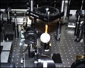
FIGURE 1. A hollow dielectric sphere is imaged using t-ray CT. The sphere is attached to a plastic tube, which is rotated by the rotation stage. The sphere was scanned with a 1-mm step size and the terahertz image was obtained for 18 different projection angles.
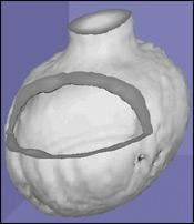
A hollow dielectric sphere was imaged using a 1-mm step size and 18 different projection angles (see Fig. 1). The amplitude of the terahertz pulse for each projection was used to reconstruct the sphere (see Fig. 2). The basic shape of the sphere and the affixed plastic tube is clearly visible.
FIGURE 2. The amplitude of the terahertz pulse at each pixel of the sphere imaged in Fig. 1 was used as the input to the filtered backprojection algorithm. Each horizontal slice of the sphere was reconstructed and the slices were combined and rendered to form a 3-D image. Part of the data has been cut away to allow the interior to be viewed.
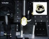
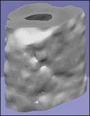
The filtered backprojection algorithm assumes that diffraction effects and Fresnel losses can be neglected, which works well for targets with features that are large relative to the wavelength of the terahertz radiation (0.3 mm at 1 THz). However, for more complex targets with fine structure the filtered back-projection algorithm is unable to accurately reconstruct the target because diffraction effects dominate the measurements (see Fig. 3 and 4).
FIGURE 3. The fine structure inside a turkey bone imaged using the t-ray CT system is of the order of the terahertz wavelength and therefore causes difficulties in reconstruction. The inset shows a view of the bone from above.
The future
The applicability of the t-ray CT technique is limited by two important restrictions: first, the limited terahertz power available and, second, the approximations made by the reconstruction algorithm. As t-ray CT operates in transmission mode it is only suitable for objects that do not attenuate or scatter the terahertz radiation too severely. This is a particular limitation for biomedical applications in which the absorption of moist tissue is prohibitive. In addition, the current simple reconstruction algorithm does not describe the full interaction of terahertz radiation with complex structures and more sophisticated methods are required before strongly diffracting objects can be imaged accurately. Fortunately, recent research is making progress on both of these fronts. Applications of this technique are foreseen in nondestructive mail and packaging inspection, semiconductor testing, manufacturing quality control, and even potentially in some biomedical applications where the absorption of terahertz is not too extreme.
FIGURE 4. The turkey bone in Fig. 3 was reconstructed and the 3-D rendered image generated. The reconstruction used the amplitude of the terahertz pulses at each pixel as the input to the filtered back-projection algorithm.
REFERENCES
1. B. Hu and M. C. Nuss, Opt. Lett. 20(16), 1716 (1995).
2. D. M. Mittleman et al, Appl. Phys. B: Lasers and Optics 68(6), 1085 (1999).
3. B. Ferguson, S. Wang, and X. Zhang, 2001 IEEE/LEOS Ann. Meeting Conf. Proc. PD1.7, (San Diego 2001).
4. D. M. Mittleman, R. H. Jacobsen, and M C. Nuss, IEEE Sel. Topics Quant. Elect. 2(3), 679 (1996)
5. Z. Jiang and X.-C. Zhang, Appl. Phys. Lett. 72(16), 1945 (1998).
6. G. T. Herman, Image Reconstruction From Projections - The Fundamentals of Computerized Tomography, Academic Press, New York (1980).
7. Q. Wu, T. D. Hewitt, and X.-C. Zhang, Appl. Phys. Lett. 69(8), 1026 (1996).
X.-C. ZHANG is the J. Erik Jonsson Chair Professor of Science at Rensselaer Polytechnic Institute, Department of Physics, Applied Physics and Astronomy, 110 8th Street, Troy, NY 12180; e-mail. [email protected]. BRADLEY FERGUSON is a visiting Fulbright scholar from Adelaide University in Australia; e-mail: [email protected].


