Detectors move toward third-generation IR-systems viability
Infrared (IR) imaging systems use thermal IR radiation—emitted by all objects in nature—to provide an IR radiation map of the viewed scene (the radiation map is actually a combination of the product of the objects' temperatures and their emissivities). These systems are often referred to as forward-looking IR (FLIR). In the modern battlefield, IR imaging systems have a wide variety of applications such as ground-, air-, and space-based surveillance systems; weapon night sights; aircraft navigation and piloting; night fire-control systems; and more.
At the heart of an IR imaging system is its detector, usually a semiconductor material sensitive to low-energy IR photons. Actually, the evolution of IR imaging systems is very closely related to progress in IR detector technology. Therefore, the "generation" definition (for example, second-generation) of an IR system is very much related to the generation definition of the IR detectors used in the system.
The primary material used for IR detectors throughout the last two decades has been the ternary II-VI compound mercury cadmium telluride (HgCdTe, or MCT), a variable-bandgap material that ranges from semimetals of HgTe to wide-bandgap materials of CdTe. At a composition of 80% Hg, the bandgap of this semiconductor is 0.1 eV, adequate for detecting IR light at a wavelength of 10 µm.
Evolution of IR systems
Difficulties in producing high-uniformity MCT—especially with a high mercury content—have resulted in problems related to the uniformity between detector elements. These problems have driven designers of IR systems to use a single-element IR detector. In this case, the scenery image is reconstructed by a serial scanning scheme in which a high-speed horizontal scanning mirror and a slow-moving vertical scanning mirror produce a video image at a full-frame rate. These images suffer from high noise resulting from poor detector performance and a very short integration time (which in turn is a result of the short dwell time). Infrared systems of this type are not even considered to be first generation.
As MCT technology was further developed, linear arrays of 60, 120, 180, and 240 elements could be produced with acceptable uniformity. This led to the development of first-generation (common-module-type) systems that are in use now for most tactical applications. To reconstruct a video image from these low-dimension detector arrays, a polygon or rotating mirror is often used to scan the horizontal axis. In the vertical axis, an interlaced mirror that doubles the video lines, along with an elec.tronic line-filling scheme, creates a standard video image. The horizontal resolution of first-generation systems was compatible with TV standards, whereas the vertical resolution was low as a result of the low number of elements in the focal-plane array. In addition, because of the short dwell time during scanning, the integration time was short, giving rise to a low sensitivity and hence low image contrast.
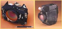
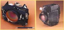
Development of second-generation detectors, focal-plane arrays, and thus higher-performance IR systems started in the late 1980s; MCT detectors as large as 480 ¥ 4 elements were developed for use in the long-wavelength IR (LWIR; 8 to 12 µm). At the same time, medium-format 320 ¥ 240-element two-dimensional (2-D) arrays were developed for medium wavelength IR (MWIR; 3 to 5 µm) that were made either of MCT or of indium antimonide (InSb; see Fig. 1).
These second-generation IR systems are currently replacing most of the first generation, giving rise to much higher performance, as well as higher fidelity of thermal imagery. All the above detectors must be cooled to the liquid-nitrogen temperature of 77 K using a closed-cycle cooler. Because these are all photon detectors (sensing each IR photon rather than the overall heat), their internal thermal noise must be much lower than the IR signal in order to be able to detect the signal, making cooling a must.
In the 1980s, Honeywell (Freeport, IL) and Texas Instruments (Dallas, TX) introduced uncooled microbolometers and uncooled pyroelectric detectors, respectively, thus opening up a new era in IR technology. For the first time, there was a real potential to position IR technology as affordable for low-end and other applications in the commercial market. Second-generation systems became an industry standard in the mid-1990s; it seemed at that time that there was no reason to develop a newer generation of IR systems and detectors.
Third-generation IR systems requirements
Military conflicts often identify shortcomings in technology. During the Gulf war, for example, coalition forces were in a situation in which they could open fire only after fully identifying a target, whereas the Iraqi forces fired based only on detection. Based on the so-called Johnson criterion (which gives detection and other probabilities for an object as a function of distance), to detect a target, only one line pair (resolution segment) must be on the target; whereas for recognition and identification, three and six line pairs, respectively, must be on the target. Therefore, identification ranges are between two and three times shorter than detection ranges. This situation opened a wide gap between the firing ranges of coalition and Iraqi forces.
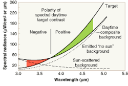
The brute-force way to increase the range of an IR system is to increase its (and hence its detectors') resolution and sensitivity, which means going to a large-format 2-D focal-plane array. In another approach, it was found that identification ranges could be increased by using multispectral detection and correlation of the images captured at different wavelengths. The multispectral detection requirements arose also from the need to overcome washout problems in which the thermal contrast of the IR image is washed out to the point that the target and the background cannot be distinguished from each other (see Fig. 2). It is clear now that for third-generation IR systems, dual or multispectral detection is an important requirement in addition to increasing system resolution and sensitivity. Multispectral IR systems can cover the MWIR, the LWIR, or both spectral windows.
Also important is the ability of an IR system to detect polarized light. Manmade objects and surfaces reflect polarized light, unlike natural backgrounds that usually leave light unpolarized. Therefore, the ability to detect polarized light can further increase the contrast of artificial objects.
Detector candidates for the third generation
There are four detector technologies that may meet specifications of third-generation IR systems: multispectral MCT, antimonide-based materials, quantum-well IR photodetectors (QWIPs), and uncooled microbolometer detectors. Uncooled detectors will probably be used for most low- and mid-level applications in the near future. For example, uncooled focal plane arrays 640 ¥ 512 pixels in size have been demonstrated. With no cryogenics needed, they are low in cost, lightweight, and compact.
Mercury cadmium telluride technology cannot take the form of large-format focal-plane arrays for the LWIR range because the uniformity and operability of such arrays are very poor. Therefore, it is accepted today that MCT will cover the MWIR (where the mercury content of the compound semiconductor is lower than for the LWIR). Dual-color MCT detectors can be made in the MWIR spectral range.
Antimonide-based materials theoretically have great potential (see Fig. 3). They can be tuned to any wavelength, have high quantum efficiency, and can cover both the MWIR and LWIR. Practically, though, material and surface problems give rise to poor detector performance. Because of the great potential of this technology, however, further effort should be invested in development.
Based on mature gallium arsenide processes, QWIP technology can yield large-format focal-plane arrays. The disadvantages of QWIP devices are that they require cooling to about 65 K and suffer from a low quantum efficiency of 10% to 20%. Such devices, however, work well for multispectral detection in both the MWIR and LWIR bands, and can be made polarization insensitive .
GABBY SARUSI is chief scientist at Elop—Electrooptic Industries Ltd., Advanced Technology Park, Kiryat Weizmann P.O.B 1165, Rehovot 76111, Israel; email: [email protected].


