Illumination Control/Computational Imaging: Multimodal microscopy using a low-cost liquid crystal display
ZICHAO BIAN, KAIKAI GUO, and GUOAN ZHENG
The condenser lens system—consisting of a high-numerical-aperture (NA) lens and a diaphragm at the lens' back focal plane—is an important component of a traditional microscope. The diaphragm allows for manual adjustment of the illumination aperture, which is important because various microscopy techniques require vastly different condenser illumination (see “Imaging approach determines illumination need”). Meeting these requirements is currently a matter of physically adjusting the condenser diaphragm, or else using specialized condenser apertures.
But what if it were possible to incorporate cost-effective, active control of the illumination system? As it happens, liquid crystal display (LCD) technology offers just this type of functionality.1 Placing an LCD (instead of a diaphragm) at the back focal plane of a condenser lens enables showing of different patterns directly on the display, without making physical adjustments. Furthermore, the LCD can be used in conjunction with novel computational imaging techniques2,3 to achieve microscopy modalities not possible in a standard microscope platform.
Imaging in five modalities
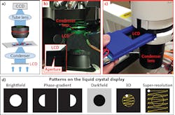
At the University of Connecticut, researchers have developed this type of setup. A low-cost LCD operates as a transparent spatial light modulator (see Fig. 1a) in both upright and inverted microscope platforms (see Figs. 1b and 1c). The patterns it generates correspond to different imaging modalities (see Fig. 1d).
For brightfield microscopy, it can display a circular pattern where the pixel transmission is turned off outside the circle. We can adjust the size of circular pattern to match different NAs of the objective lenses.
Similarly, we can display a complementary pattern for darkfield imaging. In this case, the pixel transmission needs to be turned off within the circle.
For the phase-contrast modality, we can display two complementary semicircular patterns at the LCD, capture two corresponding sample images, and get the difference between them.
Because use of an LCD enables polarization of light in the illumination path, we can place another polarizer with a different orientation at the detection path to achieve polarization imaging.
The proposed scheme can also be used to perform 3D tomographic imaging, similar to the LED-array approach demonstrated by our group.2 Here, instead of using an LED array, we can simply set a scanning aperture pattern on the LCD. For each position of the aperture, the illumination is a plane wave with an oblique incident angle. Therefore, by showing a scanning aperture on the display, we effectively illuminate the sample with different incident angles. The corresponding captured images can then be used to recover the 3D sample images using the tomographic reconstruction routine. We note that 3D tomographic imaging requires that direct transmission light enter the collection optics, thus, the scanning aperture is restricted within the NA of the collection optics (i.e., the yellow circle in Fig. 1d).
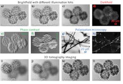
Using a starfish embryo specimen, we were able to demonstrate the versatility of the proposed platform for multimodal microscopic imaging (see Fig. 2). We applied it in both brightfield and darkfield imaging (see Fig. 2a-2d), the former with different illumination NAs corresponding to different degrees of the spatial coherence.In addition, we accomplished phase-contrast imaging along different directions for the same sample. For each of the phase contrast results, we captured a pair of raw images corresponding to the two complementary half-circular patterns at the LCD, and calculated the difference between them.
Figures 2g-2h show the polarization image of a cotton fibers sample. In Fig. 2g, the orientation of the added polarizer is the same as the LCD; in Fig. 2h, we rotated the polarizer by 90° and the sample contrast comes from rotation of the polarized light.
Figures 2i-2l depict the results of 3D tomographic imaging of the starfish embryo: We captured 49 images by showing a scanning aperture pattern on the LCD, and processed them using a tomographic reconstruction routine. Note that different parts of the starfish embryo sample are in focus at different recovered sections. This modality has the advantage of combining long depth of field with high spatial resolution (see Fig. 3). Using a small aperture at the LCD for sample illumination enables extension of the depth of focus; on the other hand, the tomographic reconstruction process enables improvement of spatial resolution to the level of conventional incoherent imaging settings.Super-resolution Fourier ptychographic imaging
The scheme is also useful for super-resolution Fourier ptychographic (FP) imaging, a computational imaging scheme we developed recently.3 This approach illuminates the sample with different oblique incident angles and captures the corresponding intensity images using a low-NA objective lens. Captured images are then combined in the Fourier domain to recover a complex image that surpasses the diffraction limit of the employed optics.
The recovery process of FP switches between spatial and Fourier domains. In the spatial domain, the captured images are used as the intensity constraint for the solution. In the Fourier domain, the confined pupil function of the objective lens is used as the support constraint for the solution. In the proposed LCD-based setup, we can simply set a scanning aperture across the LCD to get different illumination angles.
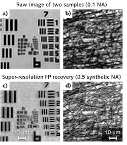
In contrast to 3D tomographic imaging, for FP the illumination NA must be larger than the collection NA for super-resolution imaging. Therefore, the scanning aperture is not restricted by the NA of the objective lens, as shown in Fig. 1d. In our implementation, we captured 121 raw images corresponding to a scanning aperture pattern at different positions on the LCD. We used a 4X, 0.1 NA objective lens in the acquisition process, and synthesized the captured images in the Fourier domain to increase the synthetic NA to 0.5. Figure 4 shows raw images and super-resolution FP reconstructions.In summary, illumination engineering is critical for obtaining high-resolution, high-quality microscopy images. The LCD-based illumination approach provides a turnkey solution with extraordinary flexibility for researchers in various fields. From an engineering point of view, it may also provide new directions for the development of multimodal microscopy, including the recently developed Fourier ptychographic imaging approach.
REFERENCES
1. K. Guo et al., Biomed. Opt. Express, 6, 574–579 (2015).
2. G. Zheng, C. Kolner, and C. Yang, Opt. Lett., 36, 3987–3989 (2011).
3. G. Zheng, R. Horstmeyer, and C. Yang, Nature Photon., 7, 739–745 (2013).
Zichao Bian and Kaikai Guo are graduate students and Guoan Zheng is an assistant professor, all in the Biomedical Engineering Department at the University of Connecticut; e-mail: [email protected]; https://sites.google.com/site/gazheng.


