Information guides detector selection
Information guides detector selection
Advances in photodiodes, PMTs, and APDs make the choice of the most-appropriate visible-wavelength detectors more difficult.
Earl Hergert
Scientists welcomed the invention of the photomultiplier tube (PMT) back in 1936; it gave them a device that could detect minute amounts of light. Today, such photon-sensing ability is assumed, and scientists seek even higher levels of light detection, looking first to solid-state devices such as the silicon photodiode and avalanche photodiode (APD). However, development of PMTs has not been static over the years, and they still compete favorably in the most-demanding applications. Scientists and designers have a growing range of options for visible light detection.
On the face of it, choosing a detector should be quite simple, because solid-state detectors generally boast very good quantum efficiency, while PMTs have large, noiseless gain. So the PMT would appear to be the obvious choice for low signal levels and the solid-state device the choice for moderate to strong light levels. However, the APD has substantial internal gain, making it effective in the low-signal-level regime. The introduction of APDs with large sensing areas and high gain makes them even more appealing.
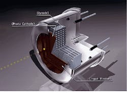
Size and power consumption have always been major considerations in choosing a detector. But once again, advances in PMTs have made them competitive with APDs for many applications. For example, PMTs with very high sensitivity and very good overall performance have been designed into TO-8 and other tiny packages that typically have contained solid-state devices (see photo at right).
Photomultiplier tubes
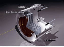
A PMT consists of a photosensitive surface (the photocathode), an electron multiplier (dynodes), and a collection electrode (the anode) all contained in an evacuated glass or metal envelope (see Fig. 1). In operation, light enters the glass input window either on the end or side of the device and is absorbed by the photocathode. An electron is emitted from the cathode and accelerated to the first dynode by an applied voltage. The electron is accelerated sufficiently to produce secondary electrons when it collides with a dynode. These secondary electrons are in turn accelerated to the next dynode. This process repeats until an electron cloud is collected at the anode.
The gain of a PMT can be estimated by µ = dn, where µ is the current amplification (gain), d is the secondary emission ratio for dynodes, and n equals the number of dynode stages. For a nine-stage PMT with a secondary emission ratio of eight, current amplification would be about 107.
Silicon photodiodes
A silicon photodiode is essentially a p-n junction consisting of a positively doped ¥region and a negatively doped n region. Between these two regions, an area of neutral charge exists, known as the depletion region. When light enters the device, electrons in the crystalline structure become excited. If the energy of the light is greater than the bandga¥energy of the material, electrons will move into the conduction band. This creates holes in the valence band where the electrons were originally located.
These electron hole pairs are created throughout the device. The pairs generated in the depletion region drift to their respective electrodes--electrons go to the n layer and the holes to the ¥layer. This results in a positive charge buildu¥in the ¥layer and a negative charge buildu¥in the n layer. The amount of charge is directly proportional to the amount of light falling on the detector. If an external circuit is connected to the ¥and n electrodes, current will flow in the circuit.
Applications such as capillary electrophoresis and high-performance liquid chromatography (HPLC), which are used in biomedical research and clinical analysis, illustrate how the performance of silicon photodiodes makes it a good choice in applications that make use of separation methods based on fluorescence and absorbance. Detection of absorbance requires the instrument to measure changes in a light beam of more than one part in 100,000.
This measurement demands very low noise at high signal levels. Only a photodiode is capable of operating at signal levels high enough to reduce the shot noise to an acceptable level. Neither PMTs nor APDs can operate at such levels. As a result, photodiodes are almost universally used in these and applications such as pulse oximeters and home glucose monitors.
In the above description, the devices are operating in the photovoltaic mode of operation. It is also possible to apply a reverse bias to the photodiode and operate in the photoconductive method mode. This mode increases the depth of the depletion region and the electric field strength between the electrodes. The advantages of photoconductive operation are higher speed, lower capacitance, and better response linearity.
Avalance photodiodes
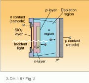
An APD is a specialized silicon PIN photodiode designed to operate with high reverse bias voltages (see Fig. 2). Large reverse voltages generate high electric fields at the p-n junction. Some of the electron hole pairs passing through or generated in this field gain sufficient energy (greater than the bandga¥energy) to create additional electron hole pairs. This process is known as impact ionization. If the newly created electron-hole pairs acquire enough energy, they also create electron-hole pairs. This is known as avalanche multiplication and is the mechanism by which APDs produce internal gain. In ternal gain is an important at tri bute when the detector is combined with an amplifier.
Defining the parameters
A necessary but often overlooked aspect of choosing a detector is defining the parameters of the application. The wavelength at which the detector will be operated and the light power that will be incident on the device are both important and may limit detector options (see "Making an informed choice," p. S11). The next ste¥is to weigh the following detector characteristics described here against the application requirements.
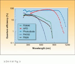
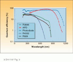
Quantum efficiency: the intrinsic ability of a detector to convert photons into electrons. It is expressed as the ratio in percent of generated electrons to incident photons (see Fig. 3). Manufacturers often do not list quantum efficiency (QE) among their specifications, instead using radiant sensitivity given in electrical current generated per incident watt of optical power, or amperes per watt (A/W). The QE is directly proportional to the photosensitivity and inversely proportional to the wavelength. If all other detector characteristics are equal, the detector with the highest QE possible is the best choice.
Gain: current amplification, or signal amplitude, one of the most misunderstood aspects of detectors. Many users mistake large signal amplitude for signal quality. Internal gain in a detector amplifies only the photogenerated signal. If the photogenerated signal is noisy, the amplified signal will be noisy as well. In reality, the benefit of gain is in raising the photogenerated signal above the noise level of the signal-processing equipment. If the signal-processing equipment is limiting the signal-to-noise ratio, the ratio can be improved by internal amplification in the detector.
Bandwidth: the electrical bandwidth of the detector. Most of the noise sources acting on an optical detector system are random and have very wide frequency distributions. Therefore, all else remaining equal, if the electrical bandwidth is increased, detection system noise can be expressed as the square root of the amplifier bandwidth.
When designing a detector system, it is critical to kee¥the bandwidth as close to the required bandwidth as possible. That is, if the light signal is changing at a frequency of 10 kHz, a detection system with a bandwidth of 1 MH¥will needlessly introduce noise. If bandwidth is not specified for a particular detector, the rise time can easily be calculated from the wavelength cutoff frequency.
Noise: spurious signal. In any light-detection application, the lower limit of signal detection is determined by the noise characteristics of the detector and its amplifiers. The three primary sources of noise in any optical detector system are photon-related shot noise, detector dark noise, and amplifier noise. Shot noise is inherent in any signal generated by the detector.
Detector dark noise also contributes to the noise of the system and is unrelated to the signal level. For the PMT and the APD, there are two primary sources of noise in addition to the shot noise created by the signal--the shot noise of the dark current generated by the detector and the noise created by the gain mechanism (excess noise) of the detector.
Excess noise is noise added to the signal by the internal amplification mechanism of a detector. For a PMT, the value is about 1.4 and decreases with increasing gain. For the APD, it has a value greater than 2 and increases with rising gain. It is also dependent on the wavelength of light being detected.
A photodiode has no internal gain, so its excess noise factor is 1. When a photodiode is in photoconductive mode (with reverse bias applied), the dark current is rather large, and the shot noise of the dark current dominates the noise of the photodiode. In photovoltaic mode (without reverse bias applied), the dark current is negligible. In this case, the Johnson noise of the photodiode shunt resistance dominates the noise term.
It should be noted that detector noise dominates when there is little or no signal. When the photogenerated current becomes greater than the noise currents, the noise in the signal will tend to dominate the detector signal-to-noise ratio. Other features commonly associated with detector noise performance include noise equivalent power (NEP) and detectivity.
These characteristics of detector noise are useful for comparing similar detectors, such as various silicon photodiodes. But, because they do not include noise from the amplifier, they should not be used to compare a PMT with a photodiode.
Transimpedance amplifiers
For the majority of applications, a trans impedance amplifier is used to convert the current output of the detector into a voltage. This amplifier preserves the linearity of the detector while maintaining very high amplifier gain.
Noise comes from three main sources--amplifier noise voltage, shot noise from the amplifier input bias current, and Johnson noise of the feedback resistor. To minimize the first source of noise, two precautions should be taken:
1. The detector shunt resistance should be much greater than the feedback resistance, which will minimize the noise voltage gain.
2. The detector capacitance should be minimized; in many applications, selection of a detector with high terminal capacitance can cause this term to dominate the total amplifier noise and degrade system performance.
To minimize shot noise from the input bias current, select an amplifier that has a very low input bias current, such as a FET input type. To control the Johnson noise, select a feedback resistor with as large a value as possible. While the noise will increase as the square root of the feedback resistance, the signal increases linearly with the feedback resistance, resulting in a net improvement in signal-to-noise ratio.
The advantage derived from internal gain detectors is in the reduction of the effective noise of the amplifier by the gain of the detector. As a result, high-gain detectors such as PMTs reduce the amplifier noise contribution to insignificance. Likewise moderate-gain detectors such as APDs greatly reduce the noise contribution of the amplifier to the total noise of the detector system. Photodiodes, which have no internal gain, are much more susceptible to the noise of the amplifier. However, their low cost and ease of use make them attractive for many applications in which light levels are moderate. o
FURTHER READING
R. W. Engstrom, Photomultiplier handbook, RCA Electrooptics and Devices, Lancaster Pa. (1980).
Photomultiplier technical handbook, Hamamatsu Photonics KK, Hamamatsu City, Japan (1994).
How to perform photon counting, Hamamatsu Photonics KK, Bridgewater, NJ (1992).
T. E. Jenkins, Optical sensing techniques and signal processing, Prentice-Hall International, New York, NY (1987).
H. P. Gowar, Optical communication systems, Prentice-Hall International, New York, NY (1984).
P. P. Webb et al., "Properties of avalanche photodiodes," RCA Review, (1994).
R. J. McIntyre, "Multiplication of noise in uniform avalanche diodes," IEEE Transactions on Electron Devices 13, 164 (1966).
G. F. Knoll, Radiation, detection, and measurement, John Wiley and Sons, New York (1979).
Cutaway of TO-8-packaged PMT shows dynode grid structure. Size need not be an overriding consideration in choosing a detector.
FIGURE 1. Light is detected and amplified internally in a conventional PMT.
FIGURE 2. In an avalanche photodiode (APD), accelerated electrons multiply in the depletion region, producing internal gain.
FIGURE 3. Quantum efficiency in these Hamamatsu detectors varies as a function of wavelength. Curves for R928 multialkali PMT, R4332 bialkali PMT, and high-performance R3896 multialkali can be compared to the photodiode and avalanche photodiode (APD) curves.
Making an informed choice
Before you select a detector for your application, determine all relevant application requirements: light power level; wavelength; range of incident light; bandwidth of the detector amplifier; application-specified mechanical requirements; size of instrument; power consumption of instrument; operating temperature range of instrument (is a cooled detector required?); and price constraints.
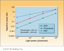
When you have narrowed your choices, based on the application`s parameters, calculate the signal-to-noise ratio under the conditions of the application (see figure). Confirm calculated results by measuring the signal-to-noise ratio in the application itself. The need for this determination seems obvious, but it is often omitted, resulting in the selection of inappropriate detectors. The ultimate test of a detector system is its signal-to-noise ratio in a particular application.
Other considerations may play a part, too, leading to a compromise choice. For instance, in a particular interference application, the APD may have the best signal-to-noise ratio, but its large temperature coefficients may make it difficult to use. A better choice might be the greater stability of the photodiode despite its lower signal-to-noise ratio.
E. H.
Calculating signal-to-noise ratio versus light power for an APD, photodiode, and PMT is necessary part of choosing a detector.
