Portable laser-based imager offers efficient hydrocarbon detection
Infrared wavelengths enable backscatter-absorption gas imaging in natural-gas and petroleum industry applications.
The ability to visualize plumes of otherwise invisible gases is an attractive possibility for a variety of applications, including leak detection, hazard control, and emergency response. The human eye cannot see most gases because they absorb at nonvisible wavelengths. However, instrumentation has been developed in recent years that operates at appropriate infrared wavelengths for gas visualization and is tailored to accentuate the gas-plume contrast. These devices are being used in a variety of industrial activities and have demonstrated the ability to increase the speed of leak-detection operations.
At Sandia National Laboratories (Livermore, CA), we have applied novel laser and sensor technologies to generate new IR active gas-imaging instrumentation. An active imager differs from a passive device because a laser is used to illuminate the scene to be viewed by the IR camera. Laser radiation backscattered from surfaces in the scene produces the image, and a gas appears in the image when it attenuates a portion of the laser backscatter.
We have focused on developing active imagers for viewing methane and larger hydrocarbon vapors. Detection of these materials is critical to the petroleum, petrochemical, and natural-gas industries—potentially the largest leak-detection markets. Active imaging for those gas species has been impossible until now because of a lack of suitably compact and efficient lasers emitting at hydrocarbon absorption wavelengths (3.1 to 3.6 µm). Available commercial active gas imagers (such as Laser Imaging Systems; Punta Gorda, FL) use CO2 lasers to operate in the 9- to 11-µm range.
Our approach has combined nonlinear frequency conversion with compact and efficient pump lasers to produce approximately 3.3-µm light of the desired spectral and temporal format. Most recently, we have used emerging quasi-phase-matched (QPM) materials with fiber amplifiers or Nd:YAG microlaser pump sources to assemble systems that a single operator can run under battery power. One such system has advanced to a series of field trials under conditions required by the petroleum-refining industry.
How it works
A successful active imager creates an image using backscattered laser photons while suppressing ambient (thermal or solar) radiation, using a method linked to the format of illumination. Systems based on a continuous-wave (CW) laser maximize the ratio of collected active to passive radiation using a raster-scanning camera. With this approach, the full power of the beam illuminates a single pixel at the target region as viewed by a single-element IR detector. Imaging occurs when this intersection is scanned across the target.
Pulsed systems use temporal discrimination—the camera is gated to collect short-duration (nanosecond) backscatter and to suppress passive radiation. The gated detector is synchronized to the laser repetition rate—a high-repetition-rate laser can use a scanned point detector while lower rates require illumination of larger regions of the target per pulse and imaging with detector arrays.
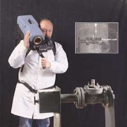
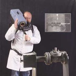
We are developing two cameras based on nonlinear light sources for hydrocarbon imaging. The first is targeted to the needs of the petroleum-refining industry, which is mandated by state and local regulations to perform regular searches for leaks at their facilities (see Fig. 1). The second system, for the Japan Gas Association (JGA), is intended for natural-gas (methane) leak inspection in homes and businesses along the delivery line up to an appliance.
Petroleum-refinery application
The hydrocarbon imager uses raster scanning with a singly resonant CW optical parametric oscillator (OPO) as its illuminator. While previously impractical, CW OPOs have been enabled by QPM materials—most notably periodically poled lithium niobate (PPLN). The combined attributes (higher nonlinear coefficient, elimination of walkoff, and imprinted spectral properties) of QPM allow the PPLN OPO to meet the requirements of a practical device. The OPO is a bowtie-ring that resonates the short-wavelength beam (1.51–1.62 µm) while emitting the long-wavelength (3.1–3.6 µm) idler, which is directed to the raster-scanned imager (made by Laser Imaging Systems) to produce the image (see Fig. 2). The 5-cm-long PPLN crystal is poled as a fan grating in which the periodicity varies continuously from one side of the element to the other, thus allowing tuning over the stated range by crystal translation.
To achieve oscillation, the OPO is pumped by a 10-W beam at 1.064-µm. Initially, this system was deployed in a van and used a water-cooled Nd:YAG pump laser powered by an onboard generator. It was successfully tested at petroleum refineries, but deemed impractical for routine use because of vehicle access limitations in refineries.
The size and efficiency of the system were improved to allow portable and battery-powered operation by replacing the Nd:YAG laser with a master-oscillator power-amplifier (MOPA) configuration consisting of a miniature Nd:YAG seed laser whose output is amplified to 10 W using a ytterbium-doped fiber amplifier. Amplifiers for the system were obtained initially from the Naval Research Laboratory (Washington, D.C.) and, later, from Keopsys (Lannion, France). The output of the MOPA has a diffraction-limited transverse beam profile, making it ideal for pumping the OPO.
The portable hydrocarbon imager is a two-component single-operator instrument that consumes about 170 W of electrical power and operates for 1.5 hours on the charge of a single lithium-ion battery pack. One component is a camera used in either a shoulder-mounted format or attached to a wheeled tripod. The other is an electronics module that is carried in a backpack.
Natural-gas detection
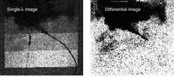
The methane imager under development for the JGA is unique in its use of differential imaging to achieve high detection sensitivity (see Fig. 3). Differential imaging is conducted by rapidly illuminating and viewing the scene with two wavelengths of light. The first ("on" wavelength) corresponds to the peak of the methane absorption line at 3270.4 nm; the second ("off" wavelength) is at a value at which methane does not absorb. The collected imagery is processed to display the logarithm of the ratio of the on- to off-wavelength pixels. This procedure nominally eliminates signal from target regions where the absorption does not differ at the two wavelengths, and retains signal from areas where the signal changes (that is, areas occluded by the gas). The resultant image displays only the gas, reducing confusion between contrasts caused by scene reflectivity variations (clutter) and those caused by the gas. This allows optimal display of the plume to the operator.
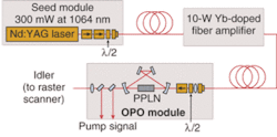
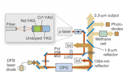
The rapid tuning needed is most simply achieved using a single-pass nonlinear conversion step rather than an OPO (see Fig. 4). The gain of PPLN allows maximum pump depletion by an optical parametric amplifier that differences the output of a 1577.3-nm distributed-feedback (DFB) diode laser from that of a pulsed (2.2-ns duration) Nd:YAG passively Q-switched microlaser. Current tuning of the DFB allows easy scanning of the OPA output frequency over a range of about 30 GHz. A digital lock-loop controls the current of the DFB to set the OPA output to the "on" wavelength. When required, the DFB current is temporarily stepped to allow generation of the "off" wavelength.
The OPA output beam is coupled to a camera that operates in a line-scanned format. A linear array consisting of 256 elements images a stripe on the target area as the stripe is illuminated with the on- and then off-wavelength pulses. This linear zone is stepped down the target to build the image. The microlaser is operated in a double-pulsed mode so that the members of on-off pairs are separated by 100 µs while pairs are emitted with a temporal separation of 550 µs. This results in imaging rates of 20 Hz (single-wavelength mode) and 10 Hz (differential mode).
Field testing of the hydrocarbon imager
The continuous-wave hydrocarbon imager is being considered as a candidate leak detector by a group organized by the American Petroleum Institute (API) and comprising representatives of petroleum companies and the U.S. Environmental Protection Agency (EPA). Industry sees imaging as an alternative to the mandated EPA Method 21, which requires the laborious use of hand-held "sniffers." A typical refinery performs Method 21 inspections quarterly on thousands of potential leak points at about a $1 million annual cost. Refineries point to a study conducted by the API as justification for coarser, but more rapid, leak-detection technology. Its results indicate that most (84%) emissions come from a very small (0.13%) fraction of components exhibiting high leak rates.
To gain EPA acceptance, an alternate technology must prove "equivalence" to existing practice. For imaging, this requirement is complicated by the disparity in data format between an imager and a sniffer, which attempts to quantify leak flux by measuring concentration near the leak. To specify the equivalence of gas imaging, the EPA is conducting analyses to correlate the concentrations of hydrocarbons measured with Method 21 with actual flux rates. This will allow a flux-detection limit required by gas imaging to be set.
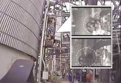
In parallel, the hydrocarbon imager has been tested in a recent series of field trials to determine detection threshold under a variety of conditions. The most notable was a test at a Texas refinery, where gas imaging was conducted simultaneously with Method 21 and leaks were also "bagged" to measure the flux (Fig. 5). During the four-day test, the imager detected 41 large leakers, and missed only two moderate ones. Results of the trial demonstrate flux detection limits between 2 and 20 gm/h hydrocarbon depending upon the windspeed background, significantly better than the estimated EPA sensitivity requirement of 40 gm/h.
The hydrocarbon imager has reached sufficient maturity for transfer to a commercial manufacturer. Field trials demonstrate the efficacy of this method in rapidly finding leaks having strengths of interest to petroleum refineries and the EPA. Additional tests are planned this year to evaluate changes in leak intensity over time in process areas monitored by gas imaging and to compare active imaging to passive imaging, which represents a competing technology. Similarly, field-testing of the line-scanned imager is scheduled to take place in Japan this spring. The consideration of a rule change allowing gas imaging as an alternative to Method 21 should be completed this spring as well. If approved, it is expected that there will be a significant demand for imaging instrumentation by the petroleum industry.
The authors are members of the Diagnostics and Remote Sensing Department at Sandia National Laboratories, P.O. Box 969 Livermore, CA 94551-9056; e-mail: [email protected].
