A light touch

New digital capabilities are generating fresh interest in holography for nondestructive testing.
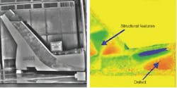
Nondestructive evaluation—often called nondestructive testing—is an increasingly critical technology in sectors of manufacturing ranging from wafer test to the inspection of aircraft components (see Fig. 1). Nondestructive evaluation (NDE) is used to inspect production parts, rather than samples culled from production, for possible material or process flaws that might otherwise be found only by damaging components.
Nondestructive evaluation is typically used in two somewhat different circumstances: when sacrificing production components is too expensive and where safety requires 100% inspection of the product line. In addition, state-of-the-art NDE is sometimes capable of detecting flaws that are difficult or even impossible to detect by more direct methods—where, say, dissecting a component might mask its failure mode.
A high level of confidence
Nondestructive evaluation provides a high level of confidence that the final product will perform as designed. This confidence is based on a thorough understanding of material behavior and of the limits of component performance for deviations in that behavior. These limits of course are dependent on the material under test and on the complexity of the component.
Modern NDE can encompass knowledge-based computing, including neural networks, for test automation, risk assessment, and so on. No matter how sophisticated the decision-making process, however, it is limited by the effectiveness of the NDE method in detecting specific flaws. The NDE response of the component must be normalized to a calibration standard prepared from a control study, or perhaps predicted by a computer simulation using finite element analysis.
Nondestructive evaluation compares an image of the component when deformed by a load to the image of the component in its rest state. Some NDE techniques, such as x-ray or neutron testing, combine the source of energy used to produce the deformation with the imaging signal itself. Other NDE test methods commonly rely on thermal loading or the deformation produced when a partial vacuum is applied over an area of the component.
Practical limitations
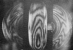
Holography has been used for NDE inspection almost since the invention of the laser made this practical—holographic inspection of aircraft tires, for example, was first performed in 1969 (see Fig. 2). Holographic test produces a pattern of intensity fringes that results from the interference of coherent light reflected from a loaded object when compared to the image of the object in its unloaded state. This "interferogram" is typically capable of displaying micron-sized distortions in the loaded test object.
The original interferometric method, however, has several limitations that make it impractical for standard NDE applications. In the decades since its invention, refinements such as speckle interferometry, comparative holography, shearography, and others were developed to circumvent some of these barriers. Recently, the techniques of digital holography combined with these improvements promises to eliminate the limitations. As a result, holographic-type inspection techniques are now found in a growing number of NDE applications.
The basic concept of digital holography is easily described but has far-reaching consequences. The term encompasses all of the capabilities arising from the use of high-resolution CCD arrays to capture the holographic image, which in turn allows the hologram to be digitally stored and immediately available for high-speed image processing. In contrast to the analysis of analog interferograms that is based on intensity distributions, digital holography allows direct computational access to the phase of the wavefront.
The digital advantage
Consider the benefit of producing real-time interferograms, for example. The conventional method records and develops a hologram and then returns it to its exact exposure position to use in viewing interference fringes as the original object is deformed—a difficult process under laboratory conditions. Digital holography allows the real-time interferogram to be displayed on a monitor while the hologram is first captured.
A digital holographic display must compute interferometric information with a sample spacing of about 5 µm. A small image with a volume of, say, a few cubic inches, will require more than 1010 data samples. A hologram contains more information than can be processed by the human vision system—for example, our depth perception relies on horizontal parallax, while a hologram contains vertical parallax as well.
Past attempts at reducing the information content of a holographic image to simplify computation proved unsatisfactory, resulting in lower resolution and signal-to-noise ratio. However great strides have been made in simplifying the data space representation. The "hogel vector" approach to bandwidth compression in particular has succeeded in reducing processing time by about two orders of magnitude (a hogel is a functional element of data in the holographic data array).
Advances in digital holography are driven to a large extent by improvements, including cost reductions, in computational power and CCD resolution. Advanced systems for digital holography illuminate the target with a laser beam from more than one direction and may use more than one CCD camera to capture displacement and deformation as well as the contour of the object. Stress and strain, fundamental vibration modes, and other results can be computed.
Comparative holography
One drawback of traditional interferograms is that the inspection of rough surfaces is limited to rather simple objects. Strong decorrelation of the interfering wavefronts from the surface microstructures results in a random speckle pattern that wipes out the interference fringes. As a consequence, interferograms were made by comparing an object with itself before and after the application of a load, precluding the comparison of production samples to a master standard, or seeing the deformation of the component during the application of the load.
Digital holography enables refinements described collectively as "comparative holography" to overcome this limitation. The unifying principle of comparative holography is the illumination of the test object with the holographic image of the standard itself, in place of the coherent laser output. The wavefront of the standard acts as a coherent mask for the deformation of the test object.
Since the holographic image is digitally stored, any location with access to the Internet is now potentially capable of reproducing a digital holographic image. The sample-to-standard comparison can take place with the sample and standard separated by great distance. To implement this technique for NDE, digital holograms of the standard (loaded and unloaded) are captured at one location. The data is transmitted to the location of the production samples and fed into a LCD modulator or similar device. A laser reads out the holograms and reconstructs the conjugated wavefront of the standard.
This wavefront of the standard is projected onto the test component from the same direction of observation that was used to record the standard hologram. The digital capture of the holographic image records of all of the wavefront information of the object automatically. Therefore an additional reference wave for the separate coding of the respective holograms is not necessary, simplifying the procedure.
Shear truth
Another serious limitation of traditional holography is its sensitivity to vibration in the test environment. The need to provide vibration isolation can be prohibitively expensive and can limit the types of loads that can be used in the test, which need to represent the real application. For example, NDE for aircraft components uses deformations produced by tensile, bending, or torsional loads, static pressure, impacts, and a wide spectrum of vibration, acoustic waves, and thermal stress.
Shearography is a holographic-type technique developed to dramatically reduce sensitivity to vibration. As one striking example, a shearography system using a hand-held scan head has been demonstrated for NDE of airframes on board an aircraft carrier at sea. Some shearography systems are capable of producing "shearograms" of components a meter square or larger at video frame rates.
Like many other refinements to holography, shearography starts with a surprisingly simple concept—a wedge of glass over one half of the camera lens will overlap a displaced or "sheared" image with the unaltered image. In actual practice, the shearing can be produced in a variety of ways. The sheared object wave is used in place of the familiar information-free reference wave (see Fig. 3).
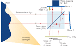
Using the shear wave as the reference makes the phase difference proportional to the first derivative of the object displacement. In physical terms, this means that the interference pattern measures the object deformation. The displacement of the object, say, by vibration, no longer contributes to the interference fringes.
Extra fine
Grating (or Moiré) interferometry, which can enhance the fringe contrast from deformations perpendicular to the direction of reflected light, has also been used in combination with shearography. Grating interferometry starts with projecting (or perhaps physically applying) a high-frequency reflection-phase grating to the surface of the object. Classical grating interferometry is easily implemented and does not even require monochromatic light to produce the Moiré fringes.
As a metrological technique, grating interferometry is useful only in specialized applications, such as the characterization of optics in the far-infrared. When combined with digital holography, however, it can produce interferograms with high contrast and low noise, and can enable a complete strain analysis in elastic and plastic regions—although it may require the surface of the object to be modified.
Must-see TV
Digital holography is referred to by a number of other terms, including electro-holography and TV holography. In addition to its use for NDE, digital holography has in recent years produced real-time 3-D images at video frame rates. State-of-the-art "holovideos" occupy a volume of about one liter, or about the size of a human hand.
The development of holovideos has been said to be roughly at the same stage as television in the 1920s. Long a staple of science fiction, there are no theoretical barriers to the development 3-D television. The trends of recent years in high-speed processing and digital imaging forecast that it is a matter of time before holographic entertainment becomes a commercial reality.