Display technology spawns laser camera
CHRIS WIKLOF
An innovative imaging platform has been developed that uses scanned beams of light and is in effect a versatile “laser camera.”1 Leveraging technology originally developed for its scanned-beam displays, Microvision has developed a scanned-beam endoscope design that meets demanding size constraints (5-mm total diameter) while also delivering good resolution (currently SVGA). While recent developments have centered on biological and medical applications, the technology represents a unique and extensible imaging architecture that has applicability across a broad range of medical and nonmedical markets, including barcode scanning, machine vision, microscopy, and scientific imaging.
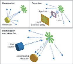
In a conventional digital camera, a field of view is flood illuminated. A small portion of the illumination power impinges upon any particular spot. The rays that impinge upon the spot can be absorbed, transmitted, reflected, or scattered. A very small portion of the light scattered from the spot is imaged through a lens and aperture to a conjugate light-sensor element, where the photons are converted to electrons. To form an image, the process is repeated in parallel, with a small portion of light from each spot simultaneously imaged onto each of a typically large array of corresponding light sensors (see Fig. 1, top).
Compared to a conventional digital camera, a laser camera works in reverse. A laser beam illuminates a single spot while a large-numerical-aperture nonimaging detector receives the scattered light energy and converts it to an electrical signal. Because all the illumination energy falls on the particular spot of interest, there is no need to form a conjugate image plane and no need to exclude light from elsewhere in the field of view with a lens and aperture. To form an image, the process is repeated sequentially, moving the beam to illuminate the next spot and the scattered energy is again measured (see Fig. 1, bottom).
Comparing the technologies, one can see that the direction of light propagation is reversed. Whereas the resolution-determining step in a conventional digital camera involves selectively receiving light energy from a spot, the resolution-determining step in a laser camera involves selectively illuminating a spot. The reversal of the rays does not affect the final image; for example, a spot that looks semitransparent and pinkish to a conventional digital camera looks semitransparent and pinkish to a laser camera.
In a three-color RGB laser camera, beams from three light sources (not necessarily lasers) are combined to form a beam of white light (see Fig. 2). The white-light beam is rapidly scanned across a field of view. Light is collected and measured by detectors through respective red, green, and blue filters. A controller converts instantaneous beam angle to a pixel position and writes the digitized RGB values to the appropriate memory location. The scanner sequentially addresses the entire field of view to capture an image frame. Subsequent image frames can be captured at video rate to capture a video image.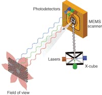
Because the light beams are combined prior to scanning, each scanned spot returns full spectral information; that is, there is no Bayer filter to collect triad color information from neighboring spots. It is also possible to extend the combined beams hyperspectrally into the IR and UV, as well as to additional bands within the visible, all without sacrificing spatial resolution or adding more scanners. Finally, multiple beams can be multiplexed to address a larger field of view.
Whereas conventional digital photography places a technology burden on the CCD or CMOS sensor array, laser photography requires a high-performance beam scanner. The beam scanner must be able to scan at high frequency to provide a high frame rate. It must also have a large (scan angle)•(mirror size) product, while maintaining acceptable static and dynamic mirror flatness to provide high resolution. Microvision currently uses proprietary single-crystal bulk-micromachined silicon microelectromechanical-system (MEMS) scanner technology developed for its scanned-beam displays (see Fig. 3).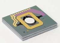
Unique attributes
A laser camera is intrinsically self-illuminating, which means that a laser camera cannot capture daylight images taken at long distances. Instead, a laser camera is a strong candidate to capture images at moderate to short distances, and especially high-magnification images. While daylight does not interfere with a laser camera’s operation—the beam scan rate is so high that the processor simply ignores DC light levels and rejects noise from artificial illumination—it also does not help it. The image captured by the laser camera is one produced by the laser camera’s scanned beam. Thus, a laser camera will not capture the appearance of dappled sunlight transmitted through leaves. Instead, the laser camera will capture the appearance of a leaf as viewed from the perspective of the light source.
Though not suitable for general-purpose, ambient-light photography, a laser camera has many attributes that are valuable to a range of commercially and scientifically important applications.
No motion blur. Because the dwell time that the beam remains on any given spot is very short (about 20 ns) there is virtually no motion blur evident in any one pixel for most types of images. Thus, it is possible to capture fast moving objects without requiring complex and bulky strobe illumination. Movement in the image that occurs during the frame time will be expressed as a skewing of the image, an artifact that can be removed during image processing.
Controlled specular reflection. Because the illumination source is a point, the amount of specular reflection in the image can be reduced significantly. For example, with a ring illuminator typically used for close-up conventional photography, many subjects exhibit a white halo that washes out important details. With a laser camera, even though the detector occupies a relatively large area, glare is virtually nonexistent.
As a corollary, low-contrast and glossy subjects, such as a barcode symbol etched in metal or silicon, can be easily captured by simply holding the surface at a slight angle to the scanning beam.
Small and self-contained. Whereas a conventional sensor array must occupy an area large enough to fit its pixels, a laser camera only requires a small sensor area and a scanning mirror. A scanning laser endoscope capable of SVGA resolution is only 5 mm in diameter. Furthermore, because a laser camera is self-illuminating, all the necessary components can be placed in a single package, thus requiring no field engineering to select, install, and adjust a light source. Such a small and self-contained package is useful for many medical, scientific, and industrial applications.
Long range/large depth of field. Because there is virtually no light lost from the illumination beam, a laser camera has greater range than the illumination range of a conventional digital camera. Similarly, conventional systems using artificial illumination at long range are typically operated with a relatively large aperture to maximize light collection, resulting in reduced depth of field. Conversely, a laser camera detector does not image the returned light and there is no need for an aperture. The laser illumination beam of a laser camera can be substantially collimated across a wide range of applications such that focus stays constant with distance, resulting in significantly improved depth of field.
Wavelength agility. If the passband of a conventional digital camera filter is narrowed, the amount of light reaching a detector is severely reduced, resulting in a low signal-to-noise ratio. Conversely, the laser illuminators typically used with a laser camera have a very narrow spectral width. This allows the system designer to select particular wavelengths with which to probe and image the field of view. Depending upon individual system architecture, it is possible to allow for a large number of imaging wavelengths, a property that lends the laser camera high specificity with respect to dye or pigment measurements. This may be especially useful in advanced medical and scientific techniques such as photodynamic therapy.
Large color gamut. Because of the narrow spectral width of the illumination sources, a laser camera’s color sensitivity is placed closer to the perimeter of a C.I.E. chromaticity diagram than the wider band filters used by a conventional digital camera to separate colors. This results in a larger triangle (for an RGB, three-color system) within the color space, which results in the ability to capture greener greens, redder reds, and bluer blues (see Fig. 4).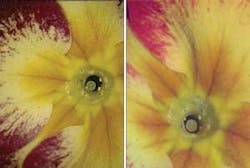
Variable field of view. The laser camera’s field of view consists of the range of spots to which the scanner directs the illumination beam and is thus determined by the drive waveform delivered to the scanner. Thus, lossless electronic zoom and variable aspect ratio may be achieved by dynamic modification of the scanner drive.
High magnification. A laser camera’s magnification can be quite high, depending upon beam shape. For example, the laser-beam waist can be made quite small and the scan angle reduced to produce a high-magnification image of a small field of view. By placing a beamsplitter between the light-beam source and the scan mirror, and picking off a return image, the laser camera can be easily configured as a tiny confocal microscope and deliver magnification sufficient to resolve embedded objects a few hundred nanometers in diameter or map the surface profile of an integrated circuit.
New frontiers
The laser-camera technology offers many new performance capabilities and benefits by exploiting a fundamentally new architecture for capturing images. These capabilities, taken individually or in combination, are expected to open a new design frontier for imaging systems with requirements that cannot be cost-effectively met by conventional integrated matrix imagers.
REFERENCE
- J. R. Lewis et al., SPIE Conf. on MOEMS Display and Imaging Systems II, 5348 (2004).
Chris Wiklof is director of patents at Microvision, 19910 N. Creek Parkway, Bothell, WA 98011; e-mail: [email protected].