Diffractive techniques improve encoder performance
Bruce Horwitz
Precision motion control is at the heart of applications such as remote surgery, magnetic data storage, and spacecraft instrumentation. Once impractical or impossible, high-performance motion-control systems are now a reality, made available by advances in miniaturized position-sensor technology. Diffraction-based optical encoders have enabled designers to improve system performance while simultaneously reducing cost and size. The technology can meet conflicting system requirements of compactness, low cost/weight, and high performance far more easily than can alternative technologies such as distance-measuring interferometers, capacitance probes, and linear variable differential transformers.
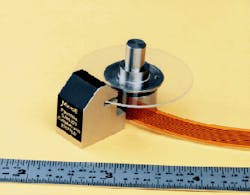
Diffraction-based linear encoders from MicroE Inc. (Needham, MA) can provide up to 0.6-nm linear resolution over a range of 0.25 m or more, while rotary encoders provide resolution as fine as 9.5 nrad over a full 2 range (see Fig. 1). With a sensor head that occupies approximately 3.5 cm3 and weighs less than 10 g, a diffractive optical encoder can be tucked into small spaces and is more stable and robust than alternative technologies.
Basic design
An encoder measures the relative motion between two parts of a mechanical system. In a conventional, geometrical-optics-based device, a light shines through slits on a moving code disk, or scale. The shadows of the slits pass over a fixed group of matching slits on a stationary scale, and a detector behind the fixed slits and a detector behind the fixed slits senses the resultant optical modulation.
This method works well enough for coarse resolution systems, but problems occur as the method is applied to higher resolutions. To in crease system resolution, the slits must be narrowed; eventually diffraction effects begin to dominate, degrading the sinusoidal fidelity of the signal and its dependence on alignment, which severely limits the subcycle resolution. Because the effects of diffraction worsen with increasing optical pathlength, a partial solution for the traditional encoder has been to move the fixed scale closer and closer to the moving scale. This approach, however, ultimately leads to expensive and unacceptably tight mechanical tolerances.
Diffractive optical encoders are based on physical optics and use the interference between two diffractive orders produced by a grating to generate a nearly perfect sinusoidal signal on a photodetector array inserted in the fringe pattern (see Fig. 2). Collimated output from a diode-laser source passes through a phase grating that diffracts the light into discrete orders. The grating design suppresses the zeroth and all even orders. With the zeroth order suppressed, a region exists beyond the diverging third order where only the +1 and -1 orders overlap to create a nearly pure sinusoidal interference. A photodetector array placed within this region captures four samples of the sinusoid.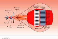
During operation, the grating moves relative to the sensor, which includes the laser and detector. As the grating changes position, relative phase shifts in the first-order beams cause the interference fringes to move on the detector array in the direction of grating motion. As these fringes pass across the focal-plane array, processing the four detected samples yields a measure of the spatial phase of those fringes (and the grating) relative to the detector array. Standard electronics amplify and normalize the sinusoids, and an interpolator, usually using a sampling algorithm called a four-bin process, estimates the phase to the desired level of resolution.1
In comparison to Michelson interferometers and traditional geometric encoders, the diffractive design is simple and compact. The region of interference is large, and nearly sinusoidal interference is obtained everywhere within this region, making alignment tolerances an order of magnitude more relaxed than those required by either competing technology.
Devil is in the details
The source module of the patented MicroE encoder comprises a laser, collimating optics, and a special Wavefront Compensator (WFC).2 The laser source is a 10-mW, 780-nm gallium arsenide diode laser (Rohm Corp.; Antioch, TN). When operated in a derated mode, these lasers have lifetimes of more than 100,000 hours and have reasonable wavelength stability with temperature. A glass aspheric lens collimates the beam along the axis of the grating, offering high immunity to thermal defocusing.
The WFC is a diffractive optic that apertures the beam to create two separate beams and redirects them to generate the optimum fringe period on our detector array (see Fig. 3). This optimization effectively decouples the grating period from the fringe period, permitting the use of any grating with one standard detector. The WFC also eliminates the need for spatial filters between the grating and the detector to remove unwanted diffractive orders.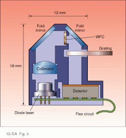
The grating in a diffractive encoder is the primary source of accuracy for the system, so MicroE fabricates its own gratings to ensure the encoders meet their specified performance levels. Depending on those requirements, the gratings are variously fabricated from photoresist on glass, ion-etched into glass, or in the case of noncritical applications, embossed into various plastics. Reflective gratings are made by back-surface coating. All gratings are designed to induce a l/2 phase delay to suppress the zeroth order, with grating periods between 5 and 20 µm, and a 50:50 duty cycle to suppress even diffractive orders.
Because of the prefiltering action of the WFC, the detector is placed directly in the diffracted light coming from the grating. The 0.35 × 0.35 × 0.15-in. hybridized detector includes four interleaved, linear diode arrays—one for each bin of the four-bin process—and the supporting power and preamplification components. Several different interpolators, which accept the quadrature signal components produced by the four-bin process are available to complete the processing (see table).
Applications
Surgical robotics is one application area in which the small size but inherent high precision of diffractive encoders is important. Telepresence surgical robots under development by the US military will allow doctors to work on battlefront injuries from sites behind the lines. In the civilian sector, the same technology would allow specialists to treat patients at any location.
MicroDexterity Systems Inc. (MDS, Memphis, TN) a startup company founded by vitreoretinal surgeon and engineer Steve Charles, has been developing advanced surgical robotics in collaboration with Sandia National Laboratories (Albuquerque, NM) and the NASA Jet Propulsion Laboratory (Pasadena, CA). Engineers from MDS have incorporated MicroE linear and rotary optical encoders into the company`s dexterity-enhancement system—a robotic hand that can perform the extraordinarily precise motions of a surgeon, without tiring and unavoidable human tremors. The compact diffractive encoder allows the device to measure all six degrees of robotic freedom in the limited space of a retinal surgery field.
Applications expanding
Another precision-encoder application is computer hard-drive servo track writing—generating servo track information on computer hard drives during manufacturing. The high precision and environmental stability of the diffractive encoder provides better performance at lower cost than Michelson distance-measuring interferometers used previously. The classical approach has been to nudge the drive`s read/write head along with a mechanical pushpin inserted through the housing, controlling the motion with position feed back from a Michelson system.
More than a year ago, MicroE introduced a two-sensor system, the Optical Push Pin, in which a null-seeking diffractive sensor that monitors a stick-on grating on the read/write arm replaces the mechanical pushpin, while a rotary encoder moves the null-seeking encoder precisely. This combination gives superior repeatability and on-position stability while simultaneously eliminating the mechanical contact and the environmental calibration requirements of the Michelson approach.
Diffractive optical encoders are an evolving technology. Resolution and accuracy will improve as new detectors, processors, and gratings are developed. MicroE and other laboratories also continue to develop a cost-effective absolute encoder.
REFERENCES
1. K. Creath, Progress in Optics, Pergamon Press, New York, NY (1988).
2. US Pat. #5,486, 923 (Jan. 23, 1996).