Optical tomography improves mammography
Optical tomography improves mammography
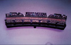
Near-infrared laser illumination and novel scanner design yield a potentially practical optical tomography system for breast-cancer screening.
Richard J. Grable
Optical tomography is a well-documented form of medical optical imaging, but only recently has the technique begun to move from concept to a practical, clinically useful imaging technique. The nonionizing nature of light, especially at near-infrared wavelengths, makes it an attractive alternative to ionizing x-rays for cancer screening. Near-infrared wavelength sources for the imaging window, from about 700 to 1100 nm, are readily available and are a viable option for medical optical imaging (MOI) devices. Scientists have been interested in optically imaging breast tissue since the Victorian era, when candle light in a dark room was used in attempts to see through the breast.1 In the last decade, researchers have tried to develop near-infrared imaging systems to perform sophisticated breast transillumination, but the work has been plagued by optical scatter, limited spatial resolution, and dependency on operator technique.2
In 1989, I developed a laser optical tomography scanner incorporating a 100-mW diode laser and a solid-state detector in a first-generation computed tomography scanner geometry. The system provided linear traverse of 512 steps of 0.015 in. and rotation of 180° in 1° increments, in a 7.68-in.-diameter scan circle. Slice-acquisition time was 3.5 min., and reconstruction required 10 min. per slice (see Fig. 1).
Lack of availability of modelocked pulsed lasers and lengthy image reconstruction times have limited initial system effectiveness and precluded device commercialization. Continuous-wave illumination and the use of modified straight-line backprojection x-ray computed tomography algorithms have yielded spatial resolution of only about 1 cm.
Design evolution
Developing a practical, clinically useful breast-imaging device entails three complex steps. A practical scanner must first be designed and built. Then software to reconstruct a clinically useful image from data predominated by scattered photons must be developed. The last step is to seek US Food and Drug Administration (FDA) clearance for clinical testing to demonstrate safety and effectiveness of the device prior to receiving FDA marketing clearance.
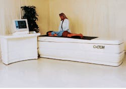
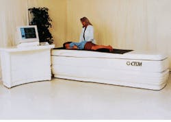
The optical tomography scanner developed by Imaging Diagnostic Systems Inc. (IDSI, Sunrise, FL) is designed to image tissue with the patient in a prone position (see photo, above), with one breast at a time pendulous in a 8-in.-diameter by 10-in.-deep scanning chamber. The method does not involve breast compression, making it more comfortable than conventional mammography. The scanning platform height of 25 in. allows patients easy access to the scanning position.
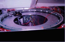
The initial system, tested in February 1995, incorporated a titanium-doped sapphire laser pumped by an argon-ion laser (both from Coherent Laser Group, Santa Clara, CA) and a solid-state detector in a fourth-generation computer tomography scanner geometry. Laser output was delivered by optical fiber to a rotating polygon mirror, producing a fan beam. The detector consisted of 600 avalanche photodiodes (APDs; Texas Optoelectronics, Garland, TX) set in a fixed ring roughly 29 in. in diameter (see Fig. 2).
The system made measurements at several thousand locations in the orbit. At each location the detectors directly in front of the laser fan beam were sampled in sequence, synchronous with the sweep of the fan. Data-acquisition time for each slice was about one second. Neither time-gating nor time-of-flight techniques was used, and the fourth-generation scanner geometry precluded collimation techniques, all of which led to unacceptable spatial resolution.
In the next system, developed in January 1996, we replaced the earlier source with a diode-pumped solid-state (DPSS) laser pumping a modelocked Ti:sapphire laser (both from Spectra-Physics Lasers, Mountain View, CA). The beam pointing and minimal optical noise characteristics of the DPSS laser reduced Ti:sapphire noise while improving beam-pointing stability. Unlike the argon-ion-pumped system, the DPSS laser does not require three-phase power or a large chiller, significantly reducing installation requirements.
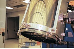
The design incorporated a third-generation geometry scanner with detector collimation. An array of several hundred APDs positioned in front of the laser fan beam acquired data on forward-scattered photons (see Fig. 3). Gain variations in the APD array resulted in image artifacts. Various schemes were used to adjust APD bias, provide individual offset and gain compensation, and implement algorithm corrections in attempts to improve image quality. Avalanche-photodiode noise and the extremely low signal levels resulted in a poor signal-to-noise ratio. Additionally, the relatively small die-size of the individual APDs and a short dwell time shortened the integration time for individual detectors. The scanner produced good images of phantoms embedded in a moderately scattering media, but highly scattering media significantly attenuated photons, which decreased the signal-to-noise ratio to an unusable value.
In the most recent design, which is moving into clinical testing, we have replaced the APDs with large-area photodiodes (Centronic Inc.; Newbury Park, CA). Laser illumination is maintained as a single beam, rather than as a beam fan of previous designs. Both the detectors and the laser beam orbit around the object being scanned, and a circular array of multiple detectors acquires data at several hundred positions in the 360° orbit. Data-acquisition time for each detector can be varied from microseconds to milliseconds, and all detectors are gated to sample at the same moment in time. Collimation devices improve spatial resolution (see Fig. 4)
Construction of a suitable scanning apparatus is a nontrivial task. The rotary motion of the laser beam and detectors must be precise, and the elevator position must be controllable to within 1 mm to allow precise positioning for contiguous or overlapping scanning. Because the detector electronics package rotates around the object being scanned, all power and signal connections must be made through electromechanical slip-rings. There is a practical limit to the number of slip-ring contacts possible in the space available, so ac power is brought in through the slip-rings and the dc power supplies and other electronics are mounted on the rotating apparatus. Signal communication is via two coaxial cables for serial communication between the computer and the scanning platform.
Safety measures on the system include sensors to ensure that the patient is properly positioned over the scanning chamber opening and fail-safe shutters to prevent scattered laser light from escaping the scanner. Other interlocks inhibit laser operation when covers are removed. We have documented the safety of the laser exposure levels impinging on in vivo tissue in our scanning configuration.
Reconstruction algorithm
The total attenuation of the scanning beam is the sum of the absorption coefficient and the scattering coefficient µs. In breast imaging, the scattering component predominates, so the reconstruction algorithm replaces µs with an effective scattering coefficient µs`, defined in terms of the average of the cosine of the scattering angle. Several teams have attempted to use an indirect inversion of the forward-scattering problem by an iterative technique that requires high computational complexity--computing times that grow exponentially as the number of volume elements in the reconstructed image.3-5
A practical imaging device, however, must reconstruct images quickly. For example, if the slice thickness is 5 mm, a typical scan could have 20 or more slices per breast. A reconstruction time of 10 min per slice requires almost 7 h per patient for complete reconstruction; at a 1-min reconstruction time, the same process would require only 40 min.
Ideally, reconstruction time should be as short as practical to maintain a throughput of three to four patients per hour. Engineers at IDSI are currently refining a noniterative, filtered back-projection algorithm that creates a map of optical properties measured at angular rotations through 360° around a scanned object. The method is far less computationally intensive than the iterative approach.
The FDA has approved the scanner for Investigational Device Exemption (IDE) testing. Initial tests involve in-house scans of a limited number of volunteers. These "calibration" scans go beyond what can be learned by scanning breast phantoms; until now, the breast has not been imaged in vivo with this approach.
The second series of IDE tests will involve a larger number of volunteers selected on the basis of various identifiable features seen in their mammogram films. Images from our scanner will be compared with the mammogram films and--where appropriate, ultrasound and magnetic resonance (MRI) images--to generate interpretive criteria for our images. This information will be the basis for a larger clinical trial designed to acquire data for a Premarket Approval (PMA) submission to the FDA. Domestic commercialization cannot commence until the system earns FDA marketing clearance; we anticipate receiving this clearance in early 1997.
REFERENCES
1. Paul French, New Scientist, 25 (March 11, 1995).
2. R. Lafreniere et al., Am. Surg. 52(3), 123 (1986).
3. J. R. Singer et al., Science 248, 990, (1990).
4. S. R. Arridge et al., Proc. SPIE 1431, 204 (1991).
5. R. L. Barbour et al., Proc. SPIE 1431, 192 (1991).
Optical tomography breast-screening system currently in clinical testing phase features large-area photodiode detectors. Collimation, single-beam illumination, and time-gating techniques increase image contrast and spatial resolution.
FIGURE 1. Images produced in 1989 by the initial optical tomography scanner include a human breast with a cyst (top) and a phantom with simulated lesions (bottom). Light areas are representative of solid lesions.
FIGURE 2. The detector on the initial optical tomography system consisted of 600 avalanche photodiodes set in a fixed ring roughly 29 in. in diameter.
FIGURE 3. Second-generation tomographic scanner detector design was modified to include an array of several hundred APDs.
FIGURE 4. Image of phantom target taken by the system shows simulated solid lesion (light region) and simulated cyst (dark region). The target consists of a 13-cm-diameter container filled with 0.5% Interlipid solution to simulate the scattering effects of tissue.
