Oversampled ADC methods benefit video applications
Oversampled ADC methods
benefit video applications
William Mandl
Though relatively new to imaging, oversample analog-to-digital conversion (OSAD) has achieved acceptance for commercial audio applications.1 Products such as 1-bit Sigma-Delta-based digital CD players and telecommunication coder-decoders (CODECs) offer low power, high accuracy, and low cost. The hindrance to applying OSAD methods to video, however, has been a misunderstanding in the community about the data rates required for the conversion process.
Historically, video has been viewed as a high-data-rate process at the multiplexed focal-plane output. When viewed at the pixel level, however, data rates are very low audio. A 30-frames-per-second staring focal plane has a 15-Hz bandwidth at the pixel. So, engineers at Amain (Simi Valley, CA) have applied OSAD on the focal plane using a multiplexed oversample A/D (MOSAD) method that puts the critical components of an OSAD at each pixel on the focal plane.2,3 Depending on the design approach, this adds very little electronics.
As an example, in an infrared complementary metal-oxide semiconductor (CMOS) design, two transistors are added. With a visible light charge-injection-device (CID) approach, a charge well is added, but no transistors are required. This small electronic content allows MOSAD to be built using conventional planar semiconductor technology, either CMOS or charge well. The significant advantage of this approach, aside from keeping oversample rates low, is that noise bandwidth is limited to signal bandwidth. Furthermore, data multiplexing is digital where no noise is added.
As focal-plane arrays increase in size, output data rate is a serious concern for analog readout, where noise bandwidth increases proportionally to the amount of data being transmitted over the wires. Putting low-power A/D on the focal plane, however, provides an easy solution to this readout bottleneck with optical output. So, MOSAD is read like a video DRAM without constraints on dynamic range performance. Furthermore, being digital at the pixel level, optical output can be placed on a per-column basis or at any level of multiplexing. Because of this wide latitude in output configuration, the output bottleneck can be avoided regardless of array size.
Specific designs aimed at solving some of the problems associated with long-wave infrared (LWIR) mercury cadmium telluride (HgCdTe) sensor arrays in high-background applications are discussed below.
Development objectives
Prior to starting a product-development program based on MOSAD, technology engineers at Amain set a 12-bit or better dynamic range as a primary objective. The design that was ultimately chosen was a one-loop MOSAD (one integrator at the pixel) that used a 1-bit comparator digital output and was projected to provide a 5 ¥ 108 electron well capacity along with reasonable latitude in the selection of the CMOS circuit technology.
To develop a low-power optical readout of the focal-plane digital data, a self-electro-optical-effect device (SEED) was selected as the optical output method.4 An array of SEEDs were to be placed on or near the readout inside the Dewar as a replacement for the output drive wires. The SEED, a passive optical modulator, would be illuminated by an external LED source. A free-space link of the array with a corresponding external sensor array would then complete the link for data readout.
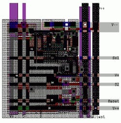
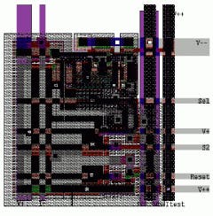
Figure 1 illustrates the layout of the pixel cell. The actual cell size is 30 µm on an edge. All of the buses were extended to fit a 40-µm pixel pitch. There are no special processing steps, design rule changes, or violations in the layout.
Each row of pixels was sequentially selected onto the read column for sampling by a comparator. The comparator is a simple switch that flips to either a logical 1 state or a logical 0 state depending on the value on the column. A precise measurement of the integrator analog value is of no interest. A rough measurement is made to determine if there is sufficient charge accumulated such that charge should be removed. This sets the state of the comparator to 1 if charge is to be removed or 0 if no charge is to be removed. This information is fed back to the pixel to control the charge subtractor. It is also read off the focal plane as the 1-bit digital value for the pixel at that sample point.
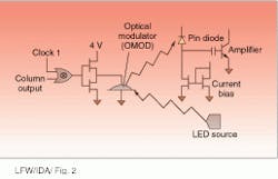
Figure 2 illustrates the focal plane output optical link, consisting of a diode LED illuminator, the SEED-based optical modulator, the pin diode receive array, and necessary optics. The digital output signal voltage of the focal-plane array controls the reflectivity of the modulator, which in turn modulates the intensity of the reflected LED light. The pin diode converts the latter off the focal plane back to the original signal, and the bit period is divided into two equal intervals.
For instance, if a pulse occurs in the first interval and not in the second one, we assign to it a "1." If the reverse occurs we assign it a "0." At the output of the pin diode, the comparison of the electron counts obtained over the two intervals of a given bit period is used to decide whether the received signal is a"1" or a "0." A bit error is declared if both intervals have the same value. The pulse position modulation (PPM) system is not susceptible to bias drifts and offset variations, because the detection process is based on the comparison of two subsequent events and therefore can be ac-coupled. The PPM is implemented by inputting the digital output of, say, the clock and a column of the focal-plane array into an exclusive NOR device.
Image display methods
The digital data generated at the pixel level by the one-loop MOSAD conversion process is the same as the bit stream generated by a Sigma-Delta converter before decimation. At this level, even though it is digital, the analog spectrum of the detector temporal response to the photon flux variation is contained in the pulse stream. The MOSAD 1-bit data are sent directly to the display. The display will be modulated on and off at rates that exceed the ability of the human eye to discern individual pulses. Consequently, the light pulses will be temporally blurred into an apparent gray-level variation with the same dynamic characteristics as the original scene. This display approach has been named Stream Vision.
Using this technology, three new concepts for infrared imaging have been demonstrated. These include on-focal-plane A/D at the pixel, passive optical readout of the digital focal plane, and digital display of video images or Stream Vision. Measurements of the digital readout array support the premise that A/D can be put on focal plane with low power dissipation and high accuracy. Noise levels achieved using on-focal-plane technology were better than the desired 12 bits. Although a thorough noise study has not been completed, spot measurements over the dynamic range showed that noise performance of better than
14 bits could be achieved. The achieved well capacity of 6 ¥ 108 required less than 30% of the pixel surface area and can be doubled with minor layout modification. Power consumption was less than 10 mW for the 128 ¥ 128 array, with 60% of this power used by the detector buffer. Wired output switching power into a 15-pF load was less than 30 µW for a 3.9 Mbaud data rate. q
WILLIAM MANDL is president of Amain Electronics Co., 1875 Angus Ave. Unit C, Simi Valley, CA 93063.
ACKNOWLEDGMENTS
Funding for this development effort was provided by the Army Night Vision and Electronic Sensors Directorate. Conrad Terrill of NVESD is the technical monitor in charge of the program. He, in collaboration with Jim Kennedy, also of NVESD, developed the signal processing and sensor requirements and set the goals for a successful conclusion of the development. LWIR HgCdTe detector arrays were provided by Muren Chu of Fermionics Corp. (Simi Valley, CA). Fermionics also hybridized the arrays and provided test support. Specially built SEED optical modulators to support the program optical interconnect were provided by Keith Goossen of Lucent Technologies (Holmdel, NJ).
REFERENCES
1. M. Chu et al., "LPE and MOCVD HgCdTe Epilayers for Dual-Band Digital FPA," IRIS (Sept. 1995).
2. An extensive review of Sigma-Delta literature is to be found in Oversampling Delta-Sigma Data Converters, J. C. Candy and G. C. Temes, eds. (IEEE Press, 1992).
3. W. Mandl and R. Ennulat, Proc. SPIE 3061, 884 (April 1997).
4. L. Lentine and D. A. B. Miller, IEEE J. Quantum Electron. 29(2), 655 (Feb.1993).
FIGURE 1. Pixel cell size of a multiplexed oversample A/D (MOSAD) device is 30 µm on an edge. Approximately 30% of the available area was used for the integration capacitor and subtraction capacitor.
FIGURE 2. Digital output signal voltage of the focal plane array controls the reflectivity of the modulator, which in turn modulates the intensity of the reflected LED light.


