Advances in image intensifiers improve spectroscopy cameras
Advances in image intensifiers improve spectroscopy cameras
Chris Calling, Al Mottola, and Donal Denvir
Intensified charge-coupled devices offer better quantum efficiency and faster gate speeds.
Cooled charge-coupled-device (CCD) cameras have long been used for multiplex spectroscopic detection. A CCD camera is, however, too slow for time-gated experiments. Even with a fast mechanical shutter, gating is limited to tens of milliseconds. In response to this limitation, Andor Technology (Belfast, Northern Ireland) and other cooled-camera manufacturers developed intensified charge-coupled devices (ICCDs).
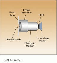
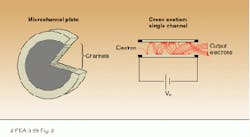
An ICCD detector head consists of two active parts--an image-intensifier tube and a CCD array (see Fig. 1). Incident photons strike the photocathode of the intensifier tube causing emission of photoelectrons. These are accelerated toward a microchannel plate (MCP) by a gate potential of a few hundred volts. The electrons are then multiplied by secondary emission in the plate, across which a potential of about 800 V is applied (see Fig. 2). The narrow channels of the MCp guide the electrons during their passage, thus retaining the original spatial distribution (that is, image information) during this amplification. After exiting the MCP, the cascade of electrons is further accelerated at a phosphor screen by (typically) a 5-kV potential. This results in an intensified image on the phosphor, which is then detected by the CCD.
The ICCD is well suited to transient spectroscopic detection because the intensifier tube can be rapidly gated electronically. Specifically, it can be turned on and off at nanosecond intervals by fast switching of the gate potential, thereby making it act as an electronic shutter. The ICCD thus combines all the benefits of cooled CCD detection with fast time resolution. In experiments using pulsed excitation, this time gating can be synchronized to a laser or flashlamp, allowing weak transient emission to be recorded, even in the presence of a relatively intense ambient background, such as in laser spectroscopy of flames. This gating also allows continuous emission from dynamic events to be sampled in narrow, well-timed windows.
Measuring performance
For most time-resolved spectroscopic applications, the two important parameters that specify ICCD performance are the gating speed and the quantum efficiency (QE). As with any low-light-level photodetector, the primary goal is to maximize the signal-to-noise ratio (S/N) to improve data quality or minimize the number of measurements that must be averaged. The QE is important because it is the principal variable that affects the S/N.
For an ICCD, the overall QE refers to the probability of an incident photon giving rise to a photoelectron that is ultimately counted by the CCD and its analog-to-digital output electronics. Sometimes, however, the QE of the intensifier photocathode alone is discussed, which refers to the probability of a photoelectron being emitted from the photocathode.
The QE is determined by the interaction between incident photons and the photocathode. Because of the quantum nature of this interaction--the photoelectric effect--QE varies with the wavelength of the incident light. At near-infrared wavelengths, the QE falls to zero because the photon energy is insufficient to release a photoelectron.
In the past few years, improvements in ICCDs have been enabled by advances in intensifier performance and enhancements in package integration. Military night vision is by far the dominant market for intensifier tubes, and, as a result, intensifiers are classified using military/aerospace terminology such as Gen I, Gen II, and so on, where Gen is short for generation.
Currently, high-end, commercial ICCDs are based on Gen II intensifier tubes. These have now reached an advanced level of performance maturity, with a wider choice of photocathodes, a larger range of tube diameters, and increased spatial resolution. Examples include the XD-4 and the red-enhanced SuperGen from Delft Electronic Products (DEP; Roden, Netherlands). In addition, Gen III intensifiers are now gradually becoming available for use in ICCDs from Andor and others. Manufactured by US aerospace suppliers such as Litton Industries Inc. (Woodland Hills, CA) and ITT Industries Inc. (White Plains, NY), these Gen III intensifiers are very difficult to obtain elsewhere because of military export restrictions. Also, it is important to note that, despite some claims to the contrary, there is currently no Gen IV tube.
Which generation?
Whether to choose Gen II or Gen III is definitely the hottest question in the ICCD marketplace right now. Given the high cost and limited availability of Gen III devices, it is critical to ask what benefits they really offer ICCD end users. But the answer is somewhat surprising for two reasons. First, the design of Gen III tubes has been specifically optimized to bring a new level of performance to night vision. At the same time, intensifier manufacturers such as DEP, which are more focused on the ICCD market, have redesigned their Gen II tubes, with products such as SuperGen, to deliver higher performance specifically optimized for ICCD users.
The main difference between Gen III and Gen II intensifiers is in photocathode material and design. In Gen III devices the active layer of the photocathode is gallium arsenide (GaAs). This offers intrinsically higher QE at longer wavelengths, to satisfy the needs of night vision.
Electron collisions with the MCp can release positive ions that are accelerated back toward the photocathode. Gallium arsenide photocathodes are very susceptible to damage caused by these ions. To avoid permanent damage to the photo cathode, an ion barrier layer is applied to the input side of the MCP. Unfortunately, this screen also acts as a partial barrier to the photoelectrons, reducing the effective QE of Gen III intensifiers. Also, to enable photoelectrons to cross this barrier, Gen III tubes are operated with a gate potential of 800 V (versus 200 V for SuperGen devices). This higher voltage is more demanding on the drive electronics and slows the gating. The screen also slows the risetime on the photocathode potential, which further contributes to slowing the gating and a "softer" on/off transition.
Although the reduction in QE caused by the ion screen has not yet been fully quantified, preliminary test results indicate that this can be as much as 50%. At wavelengths shorter than 850 nm, therefore, Gen III tubes offer no clear advantage over advanced Gen II and SuperGen devices. However, Gen III is clearly the superior option for detection in the near-infrared (850 nm to 1 µm), where it has a definite advantage in QE. In the ultraviolet (UV), Gen II devices are actually superior because Gen III GaAs photocathodes are wafer-bonded to a glass substrate, which blocks UV transmission. On the other hand, Gen II devices are available with a range of photocathodes and windows, several of which are optimized for short-wavelength response, with QE greater than 25% at 120 nm.
Slower gate speed
Other than cost and availability, the one indisputable disadvantage of Gen-III-based ICCDs is slower gate speed, because of the higher gate potential. Early ICCD designs required an external power supply to provide fast, high-voltage pulses for gating purposes. This had three drawbacks. First, it added to the complexity and size of a detection system. Second, a separate, packaged power supply increased the overall cost of the ICCD. Finally, it unnecessarily limited the maximum gating speed.
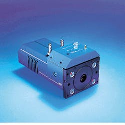
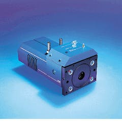
The gating speed is determined by the impedance (resistance-capacitance [RC] constant) of the drive electronics, together with the tube itself. An external gater unit with a high-voltage connector cable further adds to this RC constant. This issue is addressed in the latest generation of ICCDs, in which the gate potential is generated by a compact source within the packaged camera head (see photo on p. S19). This head is directly triggered by a TTL pulse. Using this approach, gate times as short as 2 ns are routinely available with SuperGen-based ICCDs. An additional advantage of the internal power supply is ease of integration into OEM instruments, as well as conventional laboratory setups.
This approach to minimizing the RC constant is even more important with Gen III devices, because of their inherently slower speed. Even so, the fastest gate times so far obtained with commercial Gen III ICCDs are only about 3.5 ns. o
In the latest generation of ICCDs, all high voltages are generated within the compact detector head, minimizing gate times.
FIGURE 1. The main elements of an ICCD are the intensifier tube and the cooled CCD area. Optical coupling between the two can be via fiberoptic bundles or conventional lenses.
FIGURE 2. Photoelectrons are accelerated and multiplied by secondary emission in the tubes of a microchannel plate.
CHRIS CALLING is sales and marketing manager at Andor Technology, 435 Buckland Road, Rosewood Bldg., South Windsor, CT 06074. AL MOTTOLA is senior applications specialist at Andor Technology, 168 Route 526, Allentown, NJ 08501. DONAL DENVIR is director of research and development at Andor Technology Ltd., 9 Millennium Way, Springvale Business Park, Belfast BT12 7AL, Northern Ireland.


