Kilohertz pixel scanning rates meet terahertz spectroscopic imaging
TIM JAMES, GREGOR KLATT, and ALBRECHT BARTELS
A multitude of different terahertz spectroscopy techniques have been well established in the photonics industry, and terahertz imaging has growing potential for industrial and scientific applications.1
Terahertz radiation shows strong dependence on water content and many gases, molecules, and solid-state samples exhibit a unique fingerprint in this frequency range, making terahertz radiation useful for biomedical imaging or gas sensing. Furthermore, its short wavelength leads to improved spatial resolution compared to microwave-based imaging systems, expanding the applicability of terahertz imaging to quality control systems.
Crucial points to consider when designing terahertz imaging devices are imaging speed, signal-to-noise ratio (SNR), and the type of information that can be obtained at each pixel such as intensity or spatial amplitude and phase information. And while rapid development in thermoelectric devices means that fast-scan imaging techniques in the 100 GHz range are possible with up to 1000 pixels per second imaging rates, these terahertz measurements only obtain the intensity contrast information as light is captured using thermoelectric cameras, sensor arrays, or microwave antennas. The resolution is also limited by the detection camera resolution or the limited number of antennas in the measurement array.
Another imaging method based on time-domain spectroscopy uses ultrafast lasers to generate and detect the terahertz radiation.2 Broad bandwidths up to several terahertz and collection of both amplitude and phase data means that spectroscopic imaging is feasible using this method. However, these devices gather the full-spectrum information of a sample using a pixel-by-pixel scan technique that leads to a much slower imaging speed on the order of 10 pixels per second or less, requiring several hours of acquisition time to form a full image of the sample.
But terahertz spectroscopy based on asynchronous optical sampling (ASOPS) overcomes these obstacles, combining high data acquisition rates with simultaneous access to amplitude and phase information, enabling low-noise, high-precision terahertz spectroscopy with gigahertz frequency resolution. High data acquisition rates can be achieved since there is no need for a mechanical delay between the two lasers that is normally required to sample the terahertz signal.
Compared to existing laser-based terahertz imaging devices that use gratings, optics, and require complex camera calibration, a terahertz imaging technique from Laser Quantum (Stockport, England) based on ASOPS is orders of magnitude faster and more powerful in terms of bandwidth and SNR.3-4
High-speed ASOPS technology
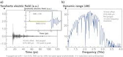
The ASOPS-based terahertz spectroscopy/imaging system uses two high-repetition-rate (1 GHz) lasers locked together in a master-slave (pump-probe) configuration with a slight frequency offset (ΔfR) between them.5 When ΔfR = 10 kHz, for example, a 1 ns terahertz transient can be acquired within only 100 µs of integration time (see Fig. 1). Measurement of the terahertz transient and the corresponding Fourier transform even at these high scan rates reveal SNR of >100 in the time domain and >30 dB in the frequency domain without averaging.
Larger SNR values can be achieved when using thicker electrooptic detection crystals and enclosing the setup and purging with nitrogen. Note that SNR in the frequency domain is usually expressed in terms of spectral power, while in the time domain it is typically related to amplitude information. And because high-repetition-rate lasers have pulse energies in the nanojoule range, it is necessary to use highly efficient photoconduction antennas for producing sufficiently large terahertz electric fields so that averaging is not required.
Experimental setup
The core layout of the terahertz time-domain spectrometer represents a reflection geometry where the terahertz beam is guided using off-axis parabolic (OAP) mirrors (see Fig. 2). Terahertz light is emitted using a photoconductive antenna (PCA) and an electrooptic crystal (EOX)—a 400 µm thick zinc-telluride (ZnTe) crystal—for terahertz detection. The sample is imaged under a 30° angle of incidence and subsides in the terahertz focal plane.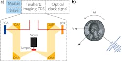
To achieve high-speed imaging of a two-dimensional (2D) sample, the experimental setup incorporates both translation and rotation mechanics that keep the sample in the focal plane of the terahertz beam. The sample is moved in one direction using a translation stage at a speed v and simultaneously rotated at speed ω. The sample is scanned along a spiral curve using carefully chosen values for v and ω such that the spatial separation of the pixel (Δx) along the translational movement axis is less than the spatial resolution of the device.
Terahertz spectroscopic imaging is typically limited to a spatial resolution of 500 µm (1 THz corresponds to a wavelength of 300 µm) due to fundamental limits if no near-field techniques are used.
The advantage of the rotational approach is the high possible scanning speed, permitting interpixel separation at the optical resolution limit while only acquiring a single terahertz trace per pixel. This high-speed terahertz spectrometer makes it possible to scan a sample even when it is moving as fast as 5 m/s or faster while maintaining the fundamental pixel resolution. So far, these high scanning speeds have only been possible with 100 GHz line-scan techniques where the spatial resolution is on the order of 3 mm and the image is formed solely by intensity contrast.
To enable pixel positions of the sample to be assigned to the measured terahertz transient, two sets of trigger signals need to be tracked throughout the measurement as the sample is continuously in motion and the pixel position is imprinted as a function of time. An optical clock signal is generated by the two lasers via cross-correlation in a two-photon absorption diode that arrives simultaneously to the terahertz signal as they originate from the same sources. The separation between two terahertz traces is τ = 1/ΔfR, which in this setup is 100 µs. The data acquisition is triggered to this signal and each collected terahertz waveform can be appropriately labeled.
By tuning the ratio ΔfR/ω, the number of measurements within the time frame of one rotation of the sample can be tuned. A further available signal of a light barrier sensor on the rotation motor indicates completion of a full revolution after time T, helping to account for slight variations in rotation speed during image acquisition when reconstructing the image. This simultaneously recorded signal is also used to monitor the rotational speed and angle position of the sample, ensuring that the position error is much smaller than the spatial resolution of the measurement.
Measurement validation
A team at Laboratoire Pierre Aigrain (Paris, France) and Laser Quantum used a 2.4-cm-diameter coin to demonstrate the capabilities of the measurement system for high-speed terahertz imaging (see Fig. 3). A rotation speed ω = 10 Hz was chosen so that within T = 100 ms, approximately 1000 waveforms are acquired during one full rotation of the sample. The translational movement of the coin is v = 1.5mm/s. These values of ω and v avoid aliasing and under-sampling of the final image.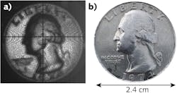
A complete scan of the coin contains approximately 130,000 pixel images with a 500 µm spatial resolution during an acquisition time of only 13 seconds. Each pixel contains amplitude and phase information of the measurement. The pixel information in the image represents the spectral intensity integrated between 2 and 3 THz to enhance the image contrast of the smaller features.
Although postprocessing after the measurement was required, it could in principle have been calculated simultaneously to the measurement of the data, assuming that the PC used has the computational power to handle the calculations while streaming the data from the measurement card to the hard drive. The observed intensity contrast in the image originates from the coin geometry.
If a sample is used with spectroscopic contrast, images can be obtained, but the measurement speed may have to be reduced for weak spectroscopic features. Because the spectroscopic capabilities of this ASOPS-based terahertz technique produce a plethora of data points, fast data acquisition based on field-programmable gate array (FPGA) data management is mandatory.6
High-speed ASOPS technology and efficient, modern terahertz antennas enable a powerful spectroscopic terahertz imaging system capable of recording more than 10,000 pixels per second with an admirable SNR of >100 in the time domain. Unlike terahertz line cameras or millimeter-wave intensity detectors, this device allows much higher spatial resolution and quantifies each imaging pixel with phase and amplitude information.7 This high-speed data imaging technique allows samples to be scanned at 5 m/s or higher velocities while preserving the fundamental limit of the terahertz radiation, which is on the order of 500 µm in the coin example described—a challenging example that can be leveraged in a variety of industrial and scientific applications.
REFERENCES
1. B. N. Behnken et al., Opt. Lett., 33, 5, 440–442 (2008).
2. D. M. Mittleman, Opt. Express, 26, 8, 9417–9431 (2018).
3. G. Ok et al., Appl. Opt., 53, 7, 1406–1412 (2014).
4. N. Kanda et al., Sci. Rep., 7, 1, 42540 (2017).
5. G. Klatt et al., Opt. Express, 17, 25, 22847–22854 (2009).
6. G. Klatt et al., IEEE J. Sel. Top. Quantum Electron., 17, 1, 159–168 (2011).
7. M. Beck et al., Opt. Express, 27, 8, 10866–10872 (2019).
Tim James is Product Engineering Manager for femtosecond laser products at Laser Quantum Ltd, Stockport, England, while Gregor Klatt is Business Development Manager representing the photonics business units within Novanta and Albrecht Bartels is General Manager, both at Laser Quantum GmbH, Konstanz, Germany; e-mail: [email protected]; www.laserquantum.com.