Seeing the invisible with quantum-enhanced imaging
Quantum effects are not as newly known as one may think. The German Maria Göppert studied physics with Max Born and wrote a dissertation on two-photon absorption in 1931.1 There were no lasers available at that time, but the essential quantum physics was on the table. In 1963, she became the second woman to receive the Nobel Prize in Physics.
It must have been an exciting time when such quantum effects were discovered in the 1920s and 1930s. Today, a variety of nonlinear effects are known that involve two, three, or more interacting photons. Some quantum effects inspire amazement, as they allow for techniques that are impossible with classical physics. And they have a touch of miracle when things can only be explained by a string of integrals and not by everyday physical experience. This hasn’t changed in these 100 years, even if lasers are now available to test the theory and make practical use of it.
How does quantum-enhanced imaging work?
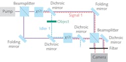
Quantum-enhanced imaging is a procedure that makes use of nonlinear optics and quantum interference to achieve insights into the literally unseen. Figure 1 shows a simplified setup in which a laser beam from the pump source is used to image an object onto a camera. The interesting point is that the camera works in a completely different spectral region than the test ray that passes through the object.In the setup, when the pump laser pulse passes the beamsplitter BS 1, it is split into beam 1 and beam 2. The photons in beam 1 may be converted in the nonlinear crystal by spontaneous nonlinear down-conversion into a pair of photons: signal 1 and idler 1. Idler 1 passes the object, taking its information (attenuation and phase shift) with it. In the second nonlinear crystal, beam 2 may create another photon pair, idler 2 and signal 2.
Here is an important point: In classical nonlinear optics, idler 1 would mix with beam 2 to create signal 2. This would be induced emission. Signal 2 would interfere with signal 1 to produce an interference pattern on the detector that contains the information from the object, but not the wave that touched the object itself.
Surprisingly, quantum physics offers an additional process that is slightly different: Pump beam 2 creates two photons, namely idler 2 and signal 2. Now, idler 2 and idler 1 are perfectly overlaid in crystal 2, forming a mixed state of indistinguishable photons—there is no induced emission involved. Still, idler 2 is entangled or coupled with the signal 2 photon.
But idler 2 isn’t idler 2 anymore. It is superposed with and indistinguishable from idler 1 and, at the same time, is entangled with signal 2. When this photonic ménage à trois is dissolved and all the idlers discarded, the information is retained in the photons of signal 2. Signal 2 and signal 1 interfere and deliver a pattern that depends on the transmission and phase shift induced by the object.
This has the important consequence that the idler wavelength can be tuned into a spectral region where no suitable detector exists. Their photon signal is not measured at all and is, in fact, discarded. This makes a big difference in quantum ghost imaging, which is another quantum imaging procedure that requires the first of the two entangled photons as a trigger signal for the recording of the second one. More details on quantum ghost imaging can be found in scientific publications, such as Lemos et al.2One may ask what the difference is between the first and the second explanation. It is a physical and measurable one: The induced emission requires much higher laser beam intensities compared to the version based on quantum interference.
Making it a real setup
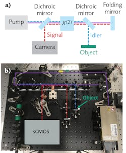
For any industrial use, it is desirable to reduce the number of components involved to a minimum, helping to reduce costs and increase stability. Figure 2a shows a sketch of such a setup that has been derived from the one shown in Figure 1. Instead of passing through two crystals, the beam is folded on mirror M and sent a second time through the same crystal. Here, the object is inspected in reflection instead of transmission. The physics remain the same.
Several special requirements have to be taken into account to turn this scheme into an experimental setup. First, the detection needs a camera suited for single-photon detection. Second, the optical path lengths need to be equal for several of the involved photons (this is inherent to the compact setup). Figure 2b shows the realized experimental setup.
On the technical side, quantum-enhanced imaging has a substantial benefit: The idler or test photons can be chosen in one spectral region that is appropriate for the test object, while the signal or image photon’s wavelength can be selected to match up with the spectral range of a commercial detector. The actual challenge for the detector is its single-photon sensitivity. The other challenge concerns the nonlinear crystal that is needed for the spontaneous downconversion process, which must support both wavelengths and feature high nonlinear coefficients to allow for an efficient nonlinear process.
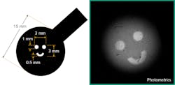
Figure 3 shows a test object and a first image recorded with quantum-enhanced imaging. It should be noted that the black-and-white image is inverted as the interference of the signal photons is tuned between constructive and destructive interference.
Images of this size can be acquired at a video rate, as the repetition rate of the pump laser is 80 MHz. And, even though individual photons are what has been examined, it should be kept in mind that the idler signal is a wave with full phase information. In other words, it is an optical wave comparable to what is used in a pinhole camera—it carries the full image information.Applications far beyond the visible
The inherent principle of the setup allows the use of ultraviolet (UV), mid-infrared, or even terahertz radiation to scan the object. Accordingly, the method offers great benefits for applications in biology or materials science. For example, in superresolution microscopy, the wavelength of the idler photons could be tuned to match exactly the required UV line of a biological specimen and thus keep the heat exposure of the specimen to a minimum. The limiting factor here is the cutoff wavelength of the nonlinear crystal. Again, while UV is used for testing, the image could be acquired within the visible spectral range.
The research in this project is part of QUILT (Quantum Methods for Advanced Imaging Solutions), a Fraunhofer lighthouse project that unites the work of six Fraunhofer Institutes. The team at the Fraunhofer-Institute for Applied Optics and Precision Engineering (Fraunhofer IOF; Jena, Germany) is currently setting up a device with 100 mW pump power at a wavelength of 405 nm. The spectral range of signal and idler photons would be between 740 and 920 nm, which would allow for a count rate of approximately 105 photons per sec*mW*nm*mm. The device will be used for testing in the field of superresolution microscopy. The new technology will be integrated into a prototype system for further development.
REFERENCES
1. M. Göppert‐Mayer, Annalen der Physik, 9, 401, 273–294 (1931); http://bit.ly/QuantumImagingRef1.
2. G. B. Lemos et al., Nature, 512, 409–412 (Aug. 28, 2014); http://bit.ly/QuantumImagingRef2.
About the Author
Andreas Thoss
Contributing Editor, Germany
Andreas Thoss is the Managing Director of THOSS Media (Berlin) and has many years of experience in photonics-related research, publishing, marketing, and public relations. He worked with John Wiley & Sons until 2010, when he founded THOSS Media. In 2012, he founded the scientific journal Advanced Optical Technologies. His university research focused on ultrashort and ultra-intense laser pulses, and he holds several patents.
Markus Gräfe
Head, quantum-enhanced imaging at Fraunhofer IOF,
Markus Gräfe is head of quantum-enhanced imaging at Fraunhofer IOF (Jena, Germany).
