Total-internal-reflection-fluorescence (TIRF) microscopy has recently gained wide acceptance as a high-sensitivity technique for selectively imaging features in a narrow “slice” of a sample. TIRF enables imaging of individual molecules, observation of cellular processes and receptor-ligand interaction on a cell’s plasma membrane, and study of diffusion mechanics of individual molecules, for instance.
TIRF-based systems generally use lasers for excitation because of their spectral purity and brightness compared to broadband sources (such as mercury and xenon arc lamps), and also because they can be easily maneuvered to achieve illumination. However, the use of lasers in fluorescence microscopy imposes new constraints on imaging systems and their components. For example, optical filters used for laser-based imaging can have different requirements than those used in wideband-illumination fluorescence microscopy. These differences affect the performance of imaging instruments.
Effective filtering
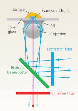
In TIRF microscopy, the excitation light path of a conventional epifluorescence microscope is modified such that only a thin section of the specimen located in close proximity to the cover glass is illuminated. As the fluorophores away from the cover glass are not illuminated, the background signal is reduced. This allows for high sensitivity imaging of a sample. Such high-sensitivity imaging requires that filters substantially block unwanted light and enhance transmission of desired light. Hard-coated filters for fluorescence imaging, pioneered by Semrock, have several advantages compared to the more conventional soft-coated filters. Hard dielectric coatings with a very high number of thin-film layers not only provide excellent, highly tailored blocking of unwanted light, but they also provide exceptional transmission, precise control over the filter spectral shape, and superior durability and longevity. The resistance to damage from high-intensity illumination for prolonged periods of time (“no burn-out”) is particularly important for laser-based imaging systems.
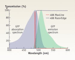
The absorption and emission spectra of fluorophores typically overlap (see Fig. 1). Because the fluorescent photons are precious, it is desirable that the separation of the excitation and emission filters be as small as possible to enable maximum capture of even weak signals close to the excitation light. Achieving tight separation requires exceptional steepness of the filter edge between blocking and transmission regions. The edge steepness of a filter is defined as the wavelength separation between a point of high blocking (such as optical density, or “OD,” of 6) and a high transmission point. With advances in the design and manufacturing techniques for hard-coated filters, edge steepness values as small as 0.2% of the laser wavelength are readily available. Such a filter designed to block a 488 nm laser with OD more than 6 is guaranteed to achieve high transmission within 1 nm of the laser line. Therefore, matching of excitation and emission filters for best performance provides a means of achieving high-fidelity imaging.A criterion conventionally used to evaluate the degree of focus of a beam of light is the Rayleigh Range, which is defined to be the distance along the beam axis from the beam waist (smallest radius) to the point where the beam radius is increased by a factor of the square root of two. This parameter indicates the depth of focus of the laser beam and thus determines whether a certain focal shift of the beam is acceptable. Durable, hard-coated dichroics specially designed for laser applications, such as BrightLine Laser dichroic beamsplitters, contribute less than one Rayleigh Range of shift in focus (relative to a perfectly flat mirror) after reflecting a collimated Gaussian laser beam with a diameter of up to 2.5 mm, thus enabling highly uniform TIRF illumination of the sample. Additionally, the reflection of these dichroics is guaranteed to be better than 98% (s-polarized light) and better than 94% (average polarization) at the laser wavelengths, and the transmission typically exceeds better than 95% with very low ripple over extremely wide passbands–out to 900 and even 1200 nm. The transition from reflection to transmission for these dichroics is exceptionally steep (better than 2.5% of the longest laser wavelength) to maximize capture of weak signals close to the laser line.
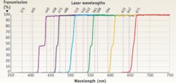
Samples labeled with multiple fluorophores generally need to be illuminated with multiple laser lines. Another type of dichroic beamsplitter that plays an important role in such multi-laser fluorescence imaging systems is the “beam combiner,” which enables the beams from multiple lasers to be brought together into a single beam in the excitation light path (Fig. 4). Dichroic beam combiners that are optimally matched to the most important lasers used for fluorescence imaging are important to efficiently combine (“multiplex” or “MUX”) multiple lasers with minimal wasted light. Without high reflection and transmission filtering, less excitation light reaches the sample and lasers must be operated harder, thus shortening laser lifetime.The long and short of it
One disadvantage of laser illumination in microscopy is that the beam has a long coherence length. In contrast to standard epifluorescence microscopy, for TIRF the excitation light is essentially completely reflected back towards the dichroic beamsplitter and the emission light path. Since dichroics are usually not designed to provide very high blocking as are excitation and emission filters, some of this backreflected light is transmitted through the dichroic and into the emission path. Interference fringe patterns resulting from multiple reflections of this light within the system can be seen at the camera. These fringe patterns are often strong enough to hamper imaging of single molecules.
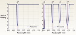
Fringe patterns and other imaging artifacts can be formed for various reasons, including accumulation of dust on an optical surface near any of the conjugate imaging planes of the microscope. However, when such interference patterns are formed by the “leakage” of excitation light past the dichroic beamsplitter in the emission light path of a fluorescence microscope, they can be effectively suppressed by additional blocking filters, including long-wave-pass and notch filters (Fig. 5). These blocking filters should not only provide deep (OD of more than 6) blocking of the laser-line, they should also have steep edges and a narrow blocking bandwidth in order to minimize obscuration of the emission signal. These filters supplement the blocking of bandpass emission filters, which by themselves typically have sufficient blocking of “well-behaved” excitation light, but may leak stray and scattered excitation light incident on the emission filter at high angles, for example. For this reason it is a good idea to position any supplemental blocking filters at a different location in the emission path from the bandpass emission filters.There has been tremendous growth in the application of fluorescence microscopy techniques during the last several decades. New imaging techniques and protocols are being developed in order to gain better insight into molecular interaction mechanisms. Samples are being labeled with multiple fluorophores from a myriad of different colors to unravel the complex cellular processes. Such studies require optical filters that are compatible with these multiple laser lines and fluorophores, as well as the optical systems and techniques upon which they are based.
ACKNOWLEDGMENT
The authors would like to acknowledge the work of Ron Witt at Semrock for the preparation of graphics for this article.
About the Author

Prashant Prabhat, Ph.D.
Business Line Leader for Semrock Catalog
Prashant Prabhat, Ph.D. is Business Line Leader of Catalog Business at Semrock. Since 2008 he has been an Applications Scientist at Semrock. He earned his Ph.D. in Electrical Engineering from the University of Texas at Dallas and completed graduate research at Ward Lab at the University of Texas Southwestern Medical Center. It was there that he invented multifocal plane microscopy (MUM), a technique that allows for real-time visualization of fast cellular dynamics in 3D. MUM has enabled the discovery of novel trafficking pathways in cells, and formed the basis for 3D super-resolution techniques. At Semrock, he advises researchers on optical filter issues from a systems perspective, and helps develop the company’s product roadmap. As a new venture manager, he also has led the development of a computer controlled tunable filter system.
Turan Erdogan
CTO and Co-Founder, Semrock
Turan Erdogan is CTO and cofounder of Semrock (a unit of IDEX Corporation; Rochester, NY).


