Optics optimizes fluorescence
Kristin Vogt
Fluorescence has long been a useful tool for a wide variety of biological applications. Continual improvements mean that fluorescent markers are becoming increasingly efficient and easier to use, and that light sources used to excite these dyes and probes are likewise advancing.
The fluorescence effect occurs when a molecule or nanoprobe is excited and emits a photon as it relaxes to a ground state. Some materials exhibit fluorescence naturally while others require a dye or a marker to fluoresce. Different molecules or probes will absorb and emit different wavelength ranges. Many of the commonly used fluorescence markers are excited with UV wavelengths and emit UV or visible wavelengths.
The setup
For many applications, fluorescence is paired with microscopy. Most fluorescence microscopy systems follow the same basic setup: the sample is exposed to an excitation source and the sample or a portion of the sample emits a fluorescence, which is collected. The most basic setup for fluorescence has an excitation channel and an emission channel separated by a dichroic beamsplitter (see figure).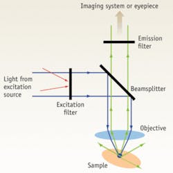
The excitation channel has an excitation source and excitation filter. The excitation filter transmits only the desired excitation wavelength. The emission channel has an emission filter, which transmits only the emission band for the fluorophore. A dichroic beamsplitter is used between the two channels to ensure the appropriate amount of exposure with the excitation source and maximum transmission of the emission wavelengths. The objective lens focuses the excitation source onto the sample and collects the emission signal. If the fluorescent dye being used has an excitation band in the ultraviolet (UV) and an emission of visible wavelengths, the objective needs to transmit both UV and visible wavelengths efficiently.
Pairing optics and materials
Fluorescence applications that use UV excitation require specialized optics designed specifically for use with UV wavelengths. For applications using both UV and visible light, particular care must be taken when selecting the optical system.
How does one select the appropriate optic? Material choice is important for applications that use UV light. Each optical material has specific transmission properties, and many types of glass readily transmit visible wavelengths but do not transmit UV wavelengths.
Also, some glass materials have an inherent autofluorescence, which can dilute the emission signal that needs to be measured. While there is no clear way to measure or define the amount of autofluorescence of a material, some materials have been found to typically have low autofluorescence. Ultraviolet fused silica, for example, has low autofluorescence and is commonly used for these types of applications.
The importance of polishing
Careful polishing is important to ensure that the optical surface is free of scratches or digs. Any surface imperfections on the optic could cause scattering, which would introduce noise into the optical system. The standard surface-quality specification, referred to as the scratch-dig specification, defines the amount of acceptable variations on the optic’s surface.
The specification has two numbers: a scratch number followed by a dig number, for example: 20-10. It is measured by a visual comparison to a set of standard surfaces in accordance with the U.S. Military Specification for the Inspection of Optical Components, MIL-PRF-13830B. A lower number indicates higher surface quality.
It is important to note, though, that these numbers do not directly correspond to the number of defects on the surface. The scratch specification includes the total length and number of allowable scratches. As a common reference, the scratch number relates to the “apparent” width size of an acceptable scratch. Dig numbers, however, do relate to a specific dig size. For example, a 10 dig number relates to a 100-µm-diameter pit.
Optics impact signals
The fluorescence emission of a fluorophore is typically a very weak signal and the optics must be designed to maximize the transmission of the signal. The emission filter is precisely designed to transmit only the emission spectra, which will help eliminate noise caused by external sources. The objective is also designed with a high numerical aperture (NA) to maximize light collection.
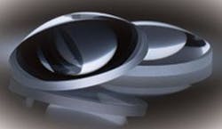
Another way to maximize signal collection is to reduce the number of optical elements in a system. Many designers use aspheric lenses because a single aspheric lens will have the focusing performance of multiple spherical lenses.
Most optical surfaces are coated with an antireflection coating, which is particularly important in the objectives used for fluorescence applications because the desired signal is already relatively weak
Make the right match
Fluorescence applications face many challenges in delivering the appropriate amount of light for excitation and emission signal collection. Because many common fluorescence dyes or probes are excited with UV wavelengths, it is critical that the optics used are specifically designed for those wavelengths. It is important to keep in mind how the optics will perform for both the excitation and emission wavelengths.
Kristin Vogt, a product line engineer with Edmund Optics, holds a BS in Biomedical Engineering from the University of Rochester. Contact her at [email protected].