Developing successful optical coherence tomography systems for ophthalmology and dermatology
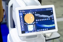
Optical coherence tomography (OCT) generates depth-resolved images noninvasively, typically up to depths of several millimeters, by utilizing the principle of low-coherence interferometry. This noninvasive imaging is highly beneficial for biomedical applications ranging from ophthalmology to dermatology (see Fig. 1).
A newer type of OCT, spectral-domain OCT (SD-OCT), is growing in popularity because of its dramatically decreased acquisition times and technical superiority. For life science system designers, understanding the proper OCT method to use and how to source the right illumination source and optical components is critical to developing a high-performing, commercially successful OCT system.
Fundamental principles of OCT
System designers should first understand the fundamental principles of how OCT systems operate. Unlike other popular depth-mapping techniques, such as radar and sonar, OCT does not rely on measuring the time at which a reflected signal (or “echo”) is detected. Instead, it utilizes the property of low temporal coherence light to interfere when the optical path length traversed by two beams is within a coherence length, creating what is known as a “coherence gate.”
This result is generally realized by splitting the light from a low-coherence light source into a reference and sample beam and allowing the reflected beams in both arms to interfere in a Mach-Zehnder configuration. The reference beam thus creates a coherence gate, as described above, so the user can resolve the light reflected from different depths within the sample. Since its inception in the 1990s1, OCT has seen widespread adoption in various fields that require noninvasive depth imaging, with the first and still most popular application being in retinal imaging for ophthalmology.
Common types of OCT
For more than three decades, several schemes have been developed to acquire depth information from a sample using OCT. However, the two main types differ in how the depth information is gathered: time-domain OCT (TD-OCT) and Fourier-domain OCT (FD-OCT).
With TD-OCT, depth-scanning is achieved by moving the reference mirror in small increments, thereby shifting the coherence gate’s position. A point detector then captures the interference signal over the entire source bandwidth. In FD-OCT, the different spectral components of light are detected separately while keeping the reference and sample fixed.
For FD-OCT, the spectral components of light can either be separated in space using the combination of a broadband light source and a spectrometer/linear CCD array for detection (called spectral-domain OCT) or in time using the combination of a swept laser source and a point detector (called swept-source OCT).
The pros and cons of each technique depend on several factors, including the capabilities of detectors and optomechanical components. In general, FD-OCT techniques lead to improved signal-to-noise ratio (SNR) and faster detection speeds compared to TD-OCT and, therefore, have been the preferred method in most commercial applications.2
Spectral-domain OCT
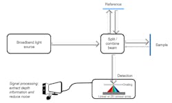
Spectral-domain OCT (SD-OCT) is replacing legacy TD-OCT systems because of its faster acquisition speeds and technical superiority. In an SD-OCT system, depth information along a single point is obtained without moving the reference or sample by simultaneously detecting the different spectral components of light on a one-dimensional or two-dimensional detector array (see Fig. 2). The Fourier transform of the detected spectrum can yield depth information in the sample, which is known as an A-scan. A two-dimensional image can be formed by acquiring adjacent A-scans, known as a B-scan. If volumetric information is desired, several B-scans can be acquired and stitched together, known as a C-scan.
Resolution of an SD-OCT system
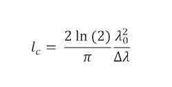
For any OCT system, the critical metrics are depth (axial) resolution, transverse (lateral) resolution, and SNR. The axial resolution of an ideal SD-OCT system depends only on the light source. With certain assumptions, it can be roughly assumed to be equal to the coherence length (lc) the light source,2 which is defined in Equation 1:
The lateral resolution of an OCT system is driven primarily by the numerical aperture (NA) of the optics used to focus light onto the sample—the higher the NA, the better the lateral resolution. Along with lateral resolution, however, it is also vital to have a large depth of focus to allow for deeper imaging into the sample. Hence, for most practical OCT systems, lower NA optics are used to optimize the system performance, including lateral resolution and imaging depth.
Choosing the right optics for an SD-OCT system
Many of the optics involved in an SD-OCT system are similar to those of TD-OCT. Like TD-OCT, there are two paths the light source follows in an SD-OCT setup: the reference and sample arms. As seen in Figure 3, light emits from the source and is split by a beamsplitter to each path arm. Optical lenses, such as plano-convex or aspheres, are used to collimate and focus light onto the sample and image sensor. The mirror in the reference arm is stationary in SD-OCT as opposed to mobile in TD-OCT, which allows for a faster acquisition rate. Selecting dielectric coatings for the reference and XY scanning mirrors will yield a system with a higher throughput compared to metallic mirror coatings.
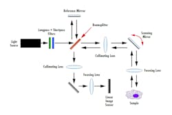
The main difference in an SD-OCT system is the addition of a diffraction grating before the image sensor. The diffraction grating spectrally disperses the interference signal into its frequency components based on wavelength. The frequency components are then detected by a linear image sensor and the Fourier transform of the frequency components is used to produce an image. Long-pass and short-pass filters can be stacked when using a broadband light source to fine-tune the wavelengths needed for different applications.
Light source considerations for SD-OCT
System designers developing SD-OCT systems should evaluate their illumination source options using five essential criteria: resolution, stability, spectral profile, the material properties of the sample, and safety.
Resolution. Equation 1 shows that a light source with a broader bandwidth and lower central wavelength would deliver improved axial resolution. For example, let’s compare a light source with 830-nm central wavelength and 100-nm bandwidth to a light source with 500-nm central wavelength and 300-nm bandwidth.
Source 1: λ0 = 830 nm, ∆λ = 100 nm à lc = 3.04 µm
Source 2: λ0 = 500 nm, ∆λ = 300 nm à lc = 0.38 µm
This comparison demonstrates the light source choice significantly impacts which features can be resolved beneath the surface. Changing the input source spectrum is the most powerful knob available for SD-OCT systems to increase resolution.
Stability. Any noise from the light source—whether amplitude noise or frequency noise—contributes to system noise. For this reason, choosing a light source with low noise is imperative, especially in applications where the sub-surface features to be imaged have a very small difference in refractive index from the bulk media (e.g., non-destructive testing of sub-surface defects in optics).
Spectral profile. The spectral profile of the light source over the usable bandwidth contributes to system performance. Generally, a flat spectral profile is preferred, as filling each spectral channel with as much power as possible improves SNR.2 So, any strong emission lines or asymmetry in the spectral shape over the usable bandwidth must be considered when choosing a light source.
Material properties of the sample. Theoretically, how deep an SD-OCT system can image is strongly dependent on the choice of imaging optics (higher depth of focus required for deeper imaging) and detector (sensitivity roll-off with depth). However, absorption in the material, which is wavelength dependent, and dispersion (refractive index dependence on wavelength) would further decrease the resolution and SNR with depth. Thus, it is crucial to consider the optical properties of the material before choosing a light source. For example, center wavelengths of 830 nm and 1050 nm are commonly used for imaging the retina to avoid water absorption peaks.
Safety. One of the most common uses of OCT is in the field of biomedical imaging (e.g., ophthalmology and dermatology). Such applications typically have stringent limits on the allowed optical power at different wavelengths due to the risk of tissue damage or injury. These restrictions often require attenuation of the input light source and is a factor that should be considered when designing an OCT system.
Other considerations. Other limitations, such as the availability of optics and detectors at desired wavelengths, also play a significant role in choosing a light source when designing an optimal SD-OCT system for any given application.
Among the commonly used light sources for biomedical OCT applications are superluminescent diodes (SLDs). When a larger bandwidth light source is required for improved resolution or to access wavelengths where no commercial SLDs are available, a supercontinuum (SC) light source is often used. For SC or other broadband light sources based on short pulses, it is not trivial to maintain stability. A bright, broadband, spectrally flat, and stable light source could provide significant benefits for applications that require access to the visible and ultraviolet wavelengths while maintaining low noise. One example application is the non-destructive detection of defects in the manufacturing of optical or ceramic components.
Ophthalmology: An application of SD-OCT
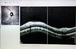
SD-OCT allows ophthalmologists to image the eye to aid the diagnosis of eye diseases, such as glaucoma and age-related macular degeneration (AMD), and to provide in situ imaging during eye surgery procedures. Due to the optically clear imaging pathway through the eye, OCT can easily be used to scan through the tissue layers of the eye.
Many SD-OCT devices on the market are used to image disorders of the retina and the anterior segment of the eye. For example, SD-OCT is used to detect glaucoma, an eye disease that damages the optic nerve due to an increase in pressure from fluid buildup.
When using SD-OCT, a thickness map of the retinal nerve fiber layer, as seen in Figure 4, can be formed to understand the severity of glaucoma and track its progression.1 SD-OCT can also be paired with surgical platforms such as laser eye surgery or phacoemulsification procedures to provide real-time images for the surgeon.
Future developments: Dermatology
SD-OCT has gained significant attention in the field of dermatology. By utilizing a 1300-nm waveband, SD-OCT allows deep penetration of the skin, enabling detailed cross-sectional and “en face” imaging down to depths of 0.4 to 2.00 mm with exceptional optical resolution.
SD-OCT strikes a balance between the depth and resolution provided by conventional methods in dermatology, including reflectance confocal microscopy (RCM) and ultrasonography. Compared to ultrasonography, SD-OCT enables superior optical resolution with more accurate and detailed images of structures within the skin, such as hair follicles, sweat glands, blood vessels, and connective tissue in the reticular dermis.
SD-OCT also allows for deeper imaging of the skin compared to RCM. This depth is particularly useful in diagnosing and monitoring diseases affecting the deeper layers of the skin, such as non-melanoma skin cancer (NMSC) and inflammatory skin diseases. However, RCM remains superior in terms of cellular resolution,3 which is essential for evaluating certain skin conditions, including melanoma.
SD-OCT can incorporate additional measures, such as polarized light OCT, to provide information about blood perfusion.4 This technique leverages the birefringent properties of collagen to assess collagen distribution within the skin. It requires high NA optics but can be useful in managing burns and understanding collagen-related skin conditions. This capability also allows the evaluation of blood vessels and their distribution within specific skin lesions. Despite some limitations and cost considerations, SD-OCT continues to evolve and improve, offering great promise for the future of dermatological imaging.
OCT is a powerful tool in the medical field for disease diagnosis and treatment monitoring to obtain real-time images of specific organs for direct visualization of tissue structures. SD-OCT, in particular, can result in high-throughput, high-performance noninvasive imaging systems.
REFERENCES
1. D. Huang et al., Science, 254, 1178–1181 (1991).
2. J. A. Izaat and M. A. Choma, Theory of Optical Coherence Tomography, Springer (2008).
3. B. Wan et al., Br. J. Dermatol., 184, 6, 1014–1022 (Nov. 2020); doi:10.1111/bjd.19553.
4. J. Olsen et al., J. Biomed. Opt., 23, 4, 1 (Apr. 2018); https://doi.org/10.1117/1.jbo.23.4.040901.
About the Author
Rebecca Charboneau
Optical Engineer, Edmund Optics
Rebecca Charboneau is an optical engineer at Edmund Optics (Barrington, NJ).
Emily Bishop
Product Support Engineer, Edmund Optics
Emily Bishop is a product support engineer at Edmund Optics (Barrington, NJ).
Shaival Buch
Principal Scientist, Energetiq Technology
Shaival Buch is principal scientist at Energetiq Technology (Wilmington, MA).