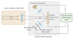
Beam Characterization: CAOS camera images laser beams with extremely high dynamic range
Accurate laser-beam characterization is essential for developing, qualifying, and testing lasers for myriad of uses. Traditional methods of looking at a laser beam include imaging the attenuated beam with a CMOS or CCD camera, as well as knife-edge, moving slit, and moving pinhole scanning techniques. Each of these forms has distinct advantages and disadvantages for different applications—as a result, different types of beam-characterization equipment are available on the market. In addition to existing hardware, new forms of beam characterization are being developed to best solve certain problems.
For example, some laser applications require 2D characterization of a beam over a high dynamic range. One traditional way of doing this is by using a 2D-scanned pinhole paired with a sensitive photodiode—however, this method is quite slow and requires high-precision scanning of the pinhole. An approach that is simpler in some ways is the use of a digital micromirror device (DMD), which is a 2D array of tiltable microelectromechanical systems (MEMS) micromirrors that can replace the function of a scanned pinhole, as each mirror can be tilted one by one to turn that particular pixel on or off. But this approach, although mechanically straightforward, is still slow.
Recently, researchers have improved the speed of the DMD-type setup by introducing various coding schemes to the DMD pixel modulation, resulting in what is called the coded-access optical sensor (CAOS) camera (which can actually be used with incoherent as well as coherent light for other imaging uses). Coding schemes for laser-beam imaging have included frequency-division multiple-access (FDMA) and time-division multiple-access (TDMA) modes.
Comparing different image-acquisition modes
Now, Nabeel Riza and Mohsin Mahzar of University College Cork (Cork, Ireland) have compared several of these image-acquisition modes, including some for the first time.1 The imaging modes include TDMA, code division multiple access (CDMA), the CDMA-TDMA mode, the FDMA-TDMA mode, the frequency modulation FM-CDMA-TDMA mode, the FM-TDMA mode, and the FDMA-CDMA-TDMA mode. For example, the CDMA approach involves turning specific combinations of pixels on and off while recording the resulting total intensity with the photodiode—a computer algorithm then decodes the data and produces an intensity map. In a second example, FM-TDMA, various pixel combinations are frequency-modulated and the signal Fourier-transformed, with frequency peaks then determined in the resulting frequency spectrum.
The two researchers found that each image-acquisition mode had its own advantages. For example, TDMA was useful for characterizing higher-power beams without saturating the photodiode, while CDMA was both fast and resulted in a high signal-to-noise ratio (SNR). FM-TDMA reproduced high precision with an extremely high dynamic range of 94.9 dB, which the researchers say allows the capture of non-Gaussian beam profiles, including Huygens–Fresnel diffraction effects.
REFERENCE
1. N. A. Riza and M. A. Mahzar, Appl. Opt. (2018); https://doi.org/10.1364/ao.57.000e20.
About the Author
John Wallace
Senior Technical Editor (1998-2022)
John Wallace was with Laser Focus World for nearly 25 years, retiring in late June 2022. He obtained a bachelor's degree in mechanical engineering and physics at Rutgers University and a master's in optical engineering at the University of Rochester. Before becoming an editor, John worked as an engineer at RCA, Exxon, Eastman Kodak, and GCA Corporation.

