Asphere Fabrication: Deterministic aspheric polishing uses multiwavelength interferometry for metrology
MATT ZABKO
The need for more-precise aspheric optics has resulted in several new polishing techniques, among them deterministic polishing. In deterministic polishing, advanced metrology techniques are used to feed data back to a polishing machine, which allows for correction of both rotational and nonrotational errors in the optic.
This correction is achieved by calculating a removal function that is based on the local geometries present on the surface and then using a combination of tool size, tool spindle speed, and part-holding spindle speed to speed up or slow down the polishing process at the location of the localized error. By using feedback from a metrology device and corrective software, CNC polishers have used deterministic polishing to directly achieve form errors of sub-100 nm without the need for additional finishing techniques, such as magnetorheological finishing (MRF).
This article details how to achieve these results with an interferometric scanning metrology system working in concert with a highly precise optics polishing machine equipped with corrective process software. A single lens is taken through the process from initial polishing to final correction, highlighting how the process achieves <100 nm of form error without the post-polishing processes that add time and expense to every lens manufactured.
Process outline and results
It is nearly impossible to correct localized defects on lenses without a full 3D map of the surface. Standard profilometry, however, doesn’t tell the whole story, since it only provides a single slice of the optical surface. Multiwavelength interferometry (MWLI), on the other hand, solves this issue by providing fast, accurate, and true 3D mapping of surface irregularities. It also offers the ability to export data in numerous formats for use with corrective software.
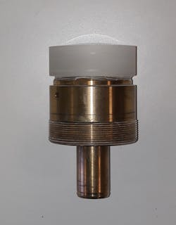
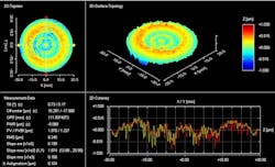
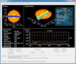
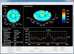
The process is started by mounting an aspheric lens on a brass arbor (see Fig. 1) using a UV-cure glue and then running a first pass on a high-precision aspheric polisher. The brass arbor is designed to interface with the hydro-expansion chuck on both the polisher and the interferometer, making the transition between the surface profiler and the polisher as seamless as possible.The lens begins with a fine-ground surface with surface irregularity of approximately 1 to 2 µm PVr1 (see Fig. 2). The first polishing run determines how much material the deterministic polishing process can remove over a given timeframe to correctly set the polishing duration and speeds. For this removal test, an oscillating tool creates a trench in an optic made of the same material as the finished part. The polisher is run in 3D mode to complete this test, and the trench depth is measured on the interferometer (see Fig. 3).
This depth is entered into the polisher’s software, which then calculates a removal coefficient. Once the removal coefficient is determined, the pre-polishing and correction process is begun to correct zonal (2D) deviations and local (3D) form errors, such as astigmatism, coma, trefoil, and so on.
Next, the optic is placed onto a hydro-expansion chuck on the interferometer and the optic’s parameters loaded directly into the instrument from the polisher, which takes less time than having an operator manually input the parameters.
The metrology software then creates a probe trajectory based on the lens’ actual shape. The object probe follows this trajectory at a constant measuring distance (the working distance of the object probe is 2.7 mm), allowing the MWLI device to succeed where other metrology devices are limited, because of inflection points and aspheric departure from the best-fit sphere.
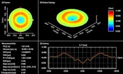
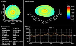
A measurement time for the full 3D surface takes 2 minutes and 32 seconds and yields 53,205 data points that can be exported in a variety of formats for further evaluation. The completed measurement indicates that the lens has a surface irregularity (PVr) of 0.9 µm. Although this is not a drastic change, mid-frequency spatial errors and fast-changing slopes have been knocked down and, overall, the surface has been smoothed out considerably compared with the fine grind process (see Fig. 4).A 3D profile is exported from the MWLI device in the Metropro.dat file format and uploaded as a correction file directly into the CNC polisher. The optic is loaded back into the polisher for a third run in 2D spindle mode for zonal corrections to eliminate major deviations, achieving a PVr <0.5 µm in under 5 minutes.
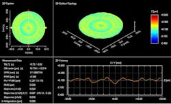
The result after one correction is shown in Figure 5. It should be noted that the PVr error is now 0.345 µm. For some, this may be suitable, but for others, a finished optic with form error <100 nm PVr is a must. To achieve that, further measurements are required, along with additional corrections using deterministic polishing to remove local form error.
The optic is loaded back into the polisher for its first correction in 3D mode using a double spiral process. This process is designed to remove rotationally symmetric errors as well as rotational unsymmetrical errors to a greater degree than via the 2D spindle process only. The polisher runs for 7 minutes on 3D polishing mode to correct the zonal errors (see Fig. 6).The polisher still has not achieved the goal of <100 nm PVr, but it is close. For a final run, a radius 40 mm tool is switched for a radius 10 mm tool to correct the smaller local deviations that remain from the previous polishing run. Again, data is loaded from the MWLI device into the polisher’s software, which is coupled with a spiral toolpath to remove the residual error left over from the previous process.
After this final polish, the sub-100 nm form error PVr goal has been achieved without requiring the use of a secondary machine to finish the polishing process (see Fig. 7). The entire process takes about 45 minutes from start to finish.The process can be outlined as follows:
- Pre-polish with a radius 40 mm tool (25 minutes)
- Measure (2 minutes, 32 seconds)
- 2D corrective polish (zonal) with a radius 40 mm tool (5 minutes)
- Measure (2 minutes, 32 seconds)
- 3D-1 corrective polish (local) with a radius 40 mm tool (7 minutes)
- Measure (2 minutes, 32 seconds)
- 3D-2 corrective polish (local) with a radius 10 mm tool (8 minutes)
- Measure (2 minutes, 32 seconds) the final result
Equipment used
The interferometric scanning metrology system used is a LuphoScan from AMETEK Taylor Hobson that uses MWLI technology to perform ultraprecise noncontact 3D form measurements, mainly of rotationally symmetric surfaces such as aspheric lenses. The LuphoScan is especially well suited for uncommon surface shapes (for example, flat apexes or profiles with points of inflection) and maximum object diameters up to 420 mm.
The precision optics polishing machine is an SPS-200 from Satisloh (Baar, Switzerland). It uses Synchrospeed or Variospeed polishing technology along with adaptive deterministic aspherical polishing technology (ADAPT) to achieve accuracy and repeatably on aspherical shapes.
REFERENCE
1. C. J. Evans, Opt. Eng., 48, 4, 043605 (Apr. 2009).
Matt Zabko is an applications engineer at AMETEK Taylor Hobson, Leicester, England; e-mail: [email protected]; www.taylor-hobson.com.
