Photonic Crystal Fibers: Porous-core photonic crystal fibers guide polarization-preserving terahertz waves

MOHAMMAD SAIFUL ISLAM, BRIAN WAI HIM NG, and DEREK ABBOTT
Photonic crystal fibers (PCFs), also known as microstructured optical fibers (MOFs), are a distinct class of optical fibers that are particularly suited to applications in the fields of sensing, biomedical imaging, time domain spectroscopy, security, DNA hybridization and cancer detection, and in optical communications. Unlike conventional optical fibers, PCFs provide high birefringence and controllable chromatic dispersion.
Solid-core PCFs experience large material loss that is not suitable for terahertz signal transmission, while hollow-core PCFs limit electromagnetic waves to short propagation distances and have high bending losses that are inversely proportional to the diameter and bending radius of the fiber. Because these undesirable features have slowed the acceptance of solid- and hollow-core PCFs, porous-core fibers have been developed.
Our team at the University of Adelaide focuses on porous-core PCFs that contain an engineered number of microstructured air holes in the core, allowing the designer to control such global fiber parameters as air hole size, pitch distance (center-to-center distance between air holes), core diameter, and air-hole shape. In turn, operational parameters such as effective material loss, birefringence, dispersion, confinement loss, numerical aperture, and other modal properties can be obtained by design as dictated by application requirements.
PCFs as waveguides
The main function of a waveguide is to transmit electromagnetic radiation with the lowest possible transmission loss and near-zero dispersion at the desired wavelength. Over the last decade, a number of waveguide structures have been designed and studied for efficient and reliable transmission of electromagnetic waves.
Initially, terahertz electromagnetic waves were guided by metallic waveguides. The various types of metallic waveguides included circular, parallel-plate, bare-metal wire, and slit waveguides. Unfortunately, metallic waveguides face a number of problems, including the fact that metal strips and slots create large Ohmic and attenuation losses; circular metallic waveguide substrates incur high dielectric losses; beam spreading in the unguided media cause divergence losses in parallel-plate waveguides; and radiative losses in the bare metallic waveguide occur because of weak confinement of the mode to the structure. A better option for terahertz transmission is the optical fiber dielectric waveguide.
Reducing transmission loss
Considering the advantage of PCFs, a number of waveguide structures have been designed for low-loss transmission of electromagnetic waves (see Fig. 1).
Dramatic reduction of the material absorption loss caused by the bulk material used in the background of a PCF is possible through (a) a hexagonal cladding and hybrid structured core; (b) a modified hexagonal cladding in which the air holes from each edge are removed, reducing loss and improving birefringence; (c) a circular-clad PCF waveguide with rotated hexagonal core; and (d) a kagome-clad PCF that reduces confinement loss 3–4X more than other competing PCF structures.1
The latter kagome configuration reduces loss by a factor of 3–4X more than the other reported cladding structures. The reason being that kagome cladding has the ability to constrict more light inside the core and restrict light from going further towards the cladding.
High birefringence
For polarization-preserving applications, PCFs need to have asymmetry between the x- and y-polarization modes. As such, a number of asymmetrically structured waveguides have been proposed to obtain high birefringence, including elliptical and rectangular air holes inside a kagome lattice (see Fig. 2).
These elliptical and rectangular air holes in the core create large asymmetry between the x and y polarization mode, thus improving the birefringence. Note that it is also possible to generate birefringence using circular-shaped air holes—however, that also requires a structure that generates asymmetry between the polarization modes.
Birefringence and sensing
By replacing the ambient air in the holes of a PCF with various analytes, a PCF can be converted to a sensor. Sensitivity is improved by optimizing the modified total internal reflection (MTIR) mechanism of the PCF to improve the interaction of light with the surrounding PCF substrate materials.
For example, if we use water (refractive index of approximately 1.33) as an analyte inside the core hole instead of air (refractive index around 1.0), the light interaction with the analyte will be stronger because of strong MTIR due to the higher refractive index of the core than the cladding. In essence, core power fraction is increased and confinement loss is decreased. Note that relative sensitivity is proportional to core power fraction and therefore, as core power fraction increases, the relative sensitivity also increases (see Fig. 3).

It has been proven that the optimal sample thickness to minimize measurement uncertainty is (2/α), where α is the absorption coefficient. Note that the absorption coefficient for ethanol is in the 20–80 cm-1 range in the 0.2–1.4 THz band. If you consider α = 20 cm-1, this will yield the worst-case largest thickness of 2/α = 2/20 = 0.1 cm = 1 mm.
Although 1 mm is a rather-large thickness value, the minima in the uncertainty vs. thickness curves are not narrow, but reasonably flattened—that is, halving the optimal thickness does not significantly degrade the uncertainty. As a result, we can reasonably halve the value of 1 mm and select 0.5 mm as a suitable sample thickness. When this 0.5 mm sample is then analyzed at around 1.4 THz, the path length of terahertz radiation is now effectively 0.05 × 80 = 4 absorption lengths. This corresponds to a 20 log e^-4 ~ = -35 dB attenuation, which is manageable.
Fiber-based terahertz heterodyne detection is known to be possible at power levels as low as 3 µW. This means that the input terahertz power into the fiber must be >160 µW, which is perfectly achievable. Because it is also well known that fiber-based heterodyne detection requires the polarization of the local oscillator to be aligned to the polarization being detected at the end of the fiber, polarization-preserving fibers must be used, solidifying the need for birefringence in PCF fiber-based terahertz sensing.
PCF sensor comparison
Characterizations of both porous-core and hollow-core PCFs for sensing show that hollow cores can improve performance in that more analytes can fill the core structure.3 In a sensor structure with a suspension type cladding with a circular-air-hole based porous core, the core interfaces can create issues with sensing, depending on the glass materials used.
There is also the option in PCF sensing of using an external or an internal sensing mechanism (see Fig. 5). In an external sensing approach, the analyte channel is outside the plasmonic material and is relatively easy to fill. Conversely, an internal sensing approach with the analyte within the air holes is more complicated because filling microstructured tiny air holes with an analyte is difficult.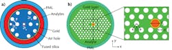
Using the surface plasmon resonance (SPR) effect between the metal and dielectric interface of a PCF can also create a SPR-based biosensor. By incorporating such metals as gold, copper, iron, and silver within the fiber core, SPR works when the electrons of the p-polarized light waves oscillate between the metal-dielectric interfaces. A tiny change of environmental refractive indices shifts the resonance wavelengths, enabling extremely sensitive SPR sensors for medical diagnostics and testing, antigen-antibody interactions, environmental monitoring, homeland security, and food safety.4
To date, PCF fabrication methods such as capillary stacking, drilling, and sol-gel methods create circular holes, while 3D printing, extrusion, and chemical vapor deposition (CVD) methods create noncircular and complex structures. As these methods improve, next-generation PCF designs will continue to progress in both sensing and transmission applications.
REFERENCES
1. M. S. Islam et al., IET Commun., 10, 16, 2179–2183 (2016).
2. M. S. Islam et al., Appl. Opt., 57, 4, 666–672 (2018).
3. M. S. Islam et al., IEEE Sensors J., 18, 2, 575–582 (Jan. 15, 2018).
4. A. A. Rifat et al., Opt. Lett., 43, 4, 891–894 (2018).
Mohammad Saiful Islam is a PhD research student, Brian Wai Him Ng is a senior lecturer, and Derek Abbott is a professor, all at the University of Adelaide, Adelaide, South Australia; e-mail: [email protected]; https://eleceng.adelaide.edu.au.