Aspheres: Finding the right tool: metrology for the manufacture of freeform optics
Freeform optical surfaces are gaining popularity with lens designers and optical system integrators as a method to solve complex optical system design problems. Fortunately, advances in optical manufacturing have opened the possibility of realizing the fabrication of these complex surfaces. However, as manufacturing techniques improve, so must the metrology necessary to measure these parts.
Manufacturing and metrology requirements
The manufacturing of freeform optics is impossible without suitable metrology—as the adage goes, "You can't make it if you can't measure it." The requirements for the metrology of freeforms can vary as much as the freeform surfaces themselves. Some of the basic requirements for freeform metrology include:
Measurement of surface irregularity. This is the typical low-order error of the surface shape, usually described by fitting to Zernike polynomials.
Measurement of surface location. Because of freeforms' lack of rotational symmetry, the surfaces may need to be measured relative to another surface or reference features.
Measurement of mid-spatial frequency errors. These error features can be induced by the subaperture tooling techniques used in the manufacturing process.
High-accuracy measurements. Depending on the freeform optics' surface-tolerance specifications, high-accuracy measurements may be required.
Fast acquisition of measurements. To keep the time and cost of manufacturing as low as possible, the metrology should be completed as quickly as possible.
A metrology plan for freeform optics fabrication may include some or all of these requirements—no one metrology device or process is the panacea for freeform metrology challenges. A freeform-optics manufacturer will have a variety of measurement tools in its metrology toolbox, a few of which will be described below.
Coordinate measurement machine (CMM)
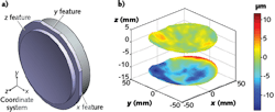
The most common tool for measuring freeform optics is the coordinate measurement machine (CMM). The CMM has a touch probe that is typically a ruby sphere attached to a scanning head—such a system provides a typical accuracy of approximately ±1.0 μm. An advantage of the CMM is its capability to measure a surface relative to the part's datum features. These datum features, or fiducials, are important for defining the freeform optic for manufacturing, as traditional optical parameters (such as wedge and center thickness) are difficult to assign to optics with little or no symmetry.1 These fiducials provide a local coordinate system that can be measured by the CMM, and provide information about the position and orientation of the freeform surface (see Fig. 1). The CMM can measure the freeform surfaces with respect to these fiducials and provide surface-to-surface registration while also obtaining irregularity maps. The flexibility of the CMM has made it the workhorse of freeform metrology.
Although the CMM is the most used metrology tool for freeform metrology, it is not without its disadvantages. Because the CMM uses a touch-probe sensor, there is a risk of scratching the optic. To minimize scratching, risk measurements are taken on a point-by-point pattern, as opposed to a continuous pattern via dragging the probe. This type of scanning is a slow process, which can make scans as slow as 2–3 seconds per point. A high-density scan to capture mid-spatial-frequency errors can take as long as 8 hours.
Another disadvantage of the CMM is accuracy. As mentioned previously, the typical accuracy limit of the CMM is about ±1.0 μm. However, there are times when the required accuracy of the freeform part must be better than what the CMM can provide. When higher-accuracy measurements are required, a high-accuracy profilometer can be used.
High-accuracy profilometer
The Panasonic UA3P high-accuracy profilometer is an ultraprecision CMM that uses an atomic-force measurement probe and displacement interferometry for positional measurement.2 This metrology tool is able to produce data accurate to approximately 50 nm for surface angles <30°. As compared to the CMM for high-density measurements, the UA3P shortens measurement time from one day down to a couple of hours.
The importance of high-accuracy surface measurements on freeforms becomes evident when measuring the mid-spatial-frequency errors of an example optic (see Fig. 2). Both measurements used 40-minute acquisition time and the UA3P was able to capture 36 times more data points than the CMM. There is good agreement between the CMM and UA3P, but the higher accuracy and density of data from the UA3P allow the mid-spatial-frequency error measurement to be quantified in more detail.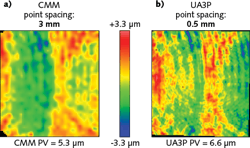
Increased accuracy and shorter measurement times are advantages of the UA3P. The UA3P fills a metrology gap between a CMM and higher-resolution tools, such as the use of a computer-generated hologram (CGH), whose cost and alignment challenges present their own issues for practical freeform metrology in manufacturing. However, unlike the CMM, the UA3P typically does not measure surfaces relative to fiducials. In addition, the UA3P typically has a smaller measurement volume than the CMM and therefore is limited to smaller freeform optics.
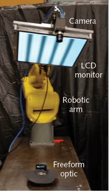
Fringe reflection deflectometry
To address the need for a fast and noncontact freeform metrology method, we are developing a fringe reflection measurement instrument. Fringe reflection (also known as deflectometry) is a technique to measure the local slope of an optical surface (see Fig. 3).3 In the technique, a camera images fringes from a LCD monitor via reflection off the surface under test. A map of the surface slopes can be determined from the deviation of the projected fringes. Surface shape can then be obtained from integrating the surface slopes.![FIGURE 3. A schematic illustrates the principle of deflectometry. A camera images fringes from a monitor via reflection off the surface under test, and a map of the surface slopes is then determined from the deviation of the projected fringes. Surface shape is then obtained from integrating the surface slopes [3].](https://img.laserfocusworld.com/files/base/ebm/lfw/image/2018/02/content_dam_lfw_print_articles_2018_02_1802lfw_bla_f3.png?auto=format,compress&fit=max&q=45?w=250&width=250)
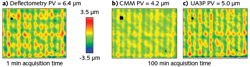
The noncontact deflectometry data seen in Fig. 4 correlates well with the CMM and UA3P data, showing the same mid-spatial-frequency error signatures. The deflectometry data took approximately 1 minute to acquire and analyze, while the CMM and UA3P took approximately 100 minutes. In an optics manufacturing environment where polishing is an iterative process, fast metrology leads to a completed part sooner.
Each of these three metrology tools for measuring freeform optics—the CMM, the UA3P profilometer, and a fringe reflection deflectometry system—provides its own advantages for specific applications of freeform metrology. As the manufacturing of freeform optics continues to evolve, so will the metrology tools for the manufacturer.
REFERENCES
1. M. Brunelle et al., "Importance of fiducials on freeform optics," Proc. SPIE, 9633, 963318 (Oct. 11, 2015).
2. See https://goo.gl/NyNTN7.
3. M. C. Knauer et al., "Phase measuring deflectometry: a new approach to measure specular free-form surfaces," Proc. SPIE, 5457, 366 (Sep. 10, 2004); doi:10.1117/12.545704.
Todd Blalock is a research and development engineer at Optimax Systems, Ontario, NY; e-mail: [email protected]; www.optimaxsi.com.
About the Author
Todd Blalock
Research and Development Engineer, Optimax Systems
Todd Blalock is a research and development engineer at Optimax Systems (Ontario, NY).