Beam Steering: Laser materials processing drives new servo control technologies
ERIC ULMER
Over the past two decades, the use of laser processing for medical, imaging, marking, and manufacturing applications has grown exponentially. This growth is supported by advances in the beam-steering technologies that make these applications possible and the unique requirements for each application motivate the development of new control techniques for servomechanism (servo) drivers that steer the laser beams.
For many years, the analog servo driver has been the benchmark for performance, with its flexible tune configurations providing targeted performance at an attractive price and form factor. However, an increasing number of applications have specific performance requirements that are best met with digital technology.
Digital servo advantages
Servo performance requirements are being driven by key applications such as marking and coding, micromachining, converting, and additive manufacturing.
Marking and coding is looking for higher throughput in terms of more characters per second (CPS) without degrading quality and/or supporting higher conveyer speeds with similar CPS. Micromachining pushes to maintain precise features in expanding material selections while increasing throughput to meet large volume demands. Converting requires close tracking for quality kiss cuts with faster web speeds. And close tracking is of vital importance to laser additive manufacturing, as it maintains consistent power density on the processed medium to provide high-quality parts.
For each of these applications, the digital control servo driver has made it possible to reach new levels of performance, largely because of the State Space Model and its key advantages over analog servos.
State Space Model and Observer overview
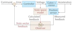
The State Space Model runs the control loop with input from a model of the galvanometer (also known as galvo) and mirror. The galvo is an electromechanical device that can be represented by differential equations that relate the galvo's electrical and mechanical parameters. For example, the galvo's induced current is derived from the coil's resistance, inductance, and back electromotive force (EMF) constant, while the galvo's rotor acceleration is derived from its torque constant, inertia, and friction.
In State Space theory, the electrical current and rotor acceleration are examples of states in the galvo system's model. A fully defined State Space Model for a galvo system could have more than 10 states. Together, these states model the interdependency of the galvo parameters and the relationship between the system's input, current state, future state, and output.
The State Space Model incorporates real-time system feedback to stay aligned with the actual system response. This feedback is brought into the State Space Model using an Observer (see Fig. 1). Every time the actual drive voltage is applied to the real galvo, a simulated voltage is applied to the model of the galvo to generate its current state. The Observer combines the measured system feedback with calculated feedback, and outputs a correction feedback to the controller.
Since the State Space Model provides insight to the future state of the system, it allows for predictive positioning control. For example, if the model knows the required acceleration for the next state of a system, it can determine if it is within its physical limits. If the drive capability is insufficient, the command input can be modified to stay within physical limits of the system. In the following sections, we explore how this example of command optimization can improve marking throughput from 30% to 100% over analog servo technology without sacrificing mark quality.
Predicted response, optimized commands
With an accurate digital model of the galvo system in place, the control loop can be manipulated to achieve the correct balance of speed and accuracy. Much of the speed increase comes from the digital servo's ability to predict the system's response to a command input.
In some digital servo designs, feedforward terms are added, which pre-distort the command to improve system response time while still maintaining stability and accuracy. In other digital servo designs, the system bandwidth is dynamically adapted as needed and applies the full drive capabilities to keep the galvo response aligned closely with the command. In both approaches, the system tracking delay is reduced.
Digital servos and zero tracking delay
Traditional marking generates vector patterns using velocity-limited commands. Because of large acceleration requirements at the vector end points, the analog servo driver must include filtering to add a delay in the galvo's response to a given command, limiting the amount of drive voltage required to change speed and direction. This delay is referred to as the system's tracking delay, and is directly related to the system's step response time and maximum linear speed.
Typical galvo systems have tracking delays between 100 and 1000 μsec. The marking job file must add compensation time for these delays to maintain pattern quality, and this limits throughput.
The digital servo reduces this tracking delay by 50-100% without giving up stability. With knowledge of the galvo and mirror dynamics accurately captured in its model, the control algorithm within the digital servo optimizes the input command profile to limit the acceleration to a value that will keep the servo within drive voltage limits. As a result, the additional filtering can be removed to greatly reduce the tracking delay for increased throughput.
In some cases, the digital servo control algorithm can eliminate the tracking error completely. For example, the DC3000 Plus digital servo driver introduces a small delay in the command stream. It uses this delay to analyze the command stream and smooth areas of high acceleration. It then dynamically adapts the bandwidth, when necessary, to apply all of the available drive voltage to lock onto the post-processed command, eliminating the tracking delays (see Fig. 2).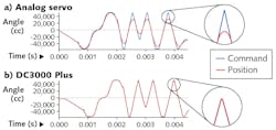
Using zero-tracking-delay algorithms, micro-precision features in the pattern that would normally be limited by the servo bandwidth are now limited only by the drive voltage, allowing up to 2X faster speeds for the smallest features in marking, micromachining, and trepanning. Applications like converting and additive manufacturing also benefit by the fact that consistent laser energy density is applied at corners and other precision features in the pattern.
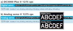
The relatively small delay settings have been optimized for the digital servo driver and achieve marking speeds of 1275 CPS. To obtain similar character quality using the analog servo driver, the delay settings would need to be increased by nearly 3X and result in marking speeds of 900 CPS. Note that the optimized command from the digital servo still maintains all the critical features of the original pattern, so the mark quality remains high while increasing throughput by 40%.
Auto-tuning overview
The State Space Model also enables auto-tuning capability. Most digital servos include this feature, which provides several benefits for production quality, integration flexibility, and field serviceability.
The Observer is used both during closed-loop operation and for auto-tuning. During closed-loop operation, the Observer is being used to make slight corrections in the control loop, whereas during auto-tuning, the Observer is used to make corrections to the galvo model.
The auto-tuning process starts with a predefined model of a galvo saved in the servo's memory. When a new a galvo is connected, the digital servo captures the unit's frequency response and other system parameters to update the model. This is followed by a fine-tuning process where the Observer compares the model's expected response to that of the actual galvo, and the model parameters are adjusted through multiple response iterations until the expected and actual response closely match each other. At that point, the system is considered tuned (see Fig. 4).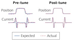
Simplified production and field service
The galvo system must be closely aligned to the model's default state for the auto-tune process to complete successfully. For this reason, auto-tuning can help identify marginal components during the assembly process. For example, large shifts in the resonant frequency could indicate an improperly installed mirror. High noise levels during the fine-tuning process could point to a marginal cable connection. In short, auto-tuning is a comprehensive verification step to ensure high-quality assemblies.
In contrast to the digital servo, the analog servo tuning process is largely isolated from component-level variations. The tuning process is essentially monitoring the position feedback of a black box system while adjusting the servo gain terms to achieve the desired response to a pre-determined command input. As long as the tuning terms can be adjusted to achieve the desired response, the system is considered verified. Even experienced tuners may not see a slight shift in resonant frequency from a marginally attached mirror.
The analog servo tuning process varies considerably with the type of control architecture and the specific criteria for each application. The flexible tuning strategies for the analog servo require significant user experience before tuning proficiency is achieved, and are typically performed by highly trained technicians using expensive test equipment. As a result, analog servo tuning is almost always performed by the servo board supplier and this tends to limit field serviceability options.
Auto-tuning of the digital servo driver greatly simplifies the tuning process, making it far more accessible to new users. It also enables flexible inventory control: since the digital servo can be tuned at any time, it can be delivered separately from the galvo and mirror in efficient quantities. For example, if a configuration differs only by mirror coating type, the laser tool manufacturer could redirect the galvos and servo to the appropriate coated mirror as demand requires. In contrast, analog servos would require the complete galvo-servo-mirror configuration to be available in inventory for both mirror coating types.
Field service is simplified with auto-tuning in that the process requires very little technical input for successful calibration. Once the field service person has identified the faulty component, they only need to replace the defective part and initiate the re-tuning process. This confines the component removal to only what is needed and leaves the rest of the configuration in a ready-to-run state, minimizing customer downtime and making replacement components easier to stock. In the same scenario, analog servos would require the entire configuration to be replaced and returned to the factory for repair and re-tuning.
Enhanced monitoring and system protection
Using the digital galvo's model and its thermal resistance, the power dissipated in the galvo can be continuously monitored to verify that the temperature remains within safe operating limits. The servo can also use the thermal model to incorporate changes in the galvo's model as it heats up during operation. Since the galvo's resistance, inductance, and torque are all affected by higher power dissipation, the servo can compensate for the changes in these parameters to keep the settling response consistent from initial power-on to high duty-cycle operation.
Digital servo technology continues to enhance existing and emerging laser materials processing applications. Next-generation digital servos are expected to improve and support new application requirements. This could include better modeling, faster update rates, higher resolution command and position feedback, predictive maintenance algorithms, integral system safety checks, and enhanced synchronization to system controllers and lasers.
Eric Ulmer is a product manager at Cambridge Technology, a Novanta company, Bedford, MA; e-mail: [email protected]; www.cambridgetechnology.com.