Thin-film Coatings: Understanding key design principles of antireflection coatings
Antireflection (AR) coatings, the most common optical coatings used in the world, range from single-wavelength operation (for narrowband lasers) to coatings functioning over very broad spectral bands such as 380–1550 nm or from 3 to 12 μm, for example.
Whether fabricated with a single layer or even tens of layers, the basic characteristics of ideal AR coatings and their real-world approximations can be described in terms of reflectance and transmittance vs. wavelength. Reflectance vs. thickness and index of refraction vs. thickness are just some of the presentations that help to illustrate both the possibilities and limitations of modern-day AR coating technology.
Antireflection basics
An uncoated surface of crown glass, such as Schott's NBK7 with index of refraction around 1.52 at 550 nm, will reflect about 4.26% of incident light across the visible spectrum. In camera and microscope lenses, this reflection will unfortunately cause ghost images and lost transmittance of the wanted image flux. To prevent such reflections, the concept of the single-layer AR coating was patented in the 1930s by Smakula, and John Strong reported a single-layer AR (SLAR) coating in 1936.1, 2
The primary underlying principle of AR coatings is that the reflection of light from the outside surface of a single coating layer interferes with the reflection from the interface between the coating layer and the substrate. The reflection can be eliminated (made to be zero) if the refractive index of the coating material (n2) is equal to the square root (SQRT) of the product of the indices of the substrate (n3) and the surrounding medium (n1, air or vacuum). That is, n2 = SQRT(n1*n3).
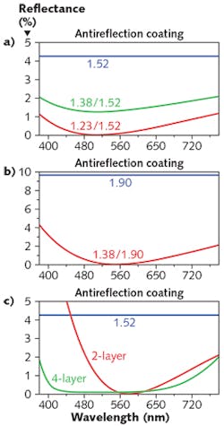
Basically, the reflectance will be zero at the wavelength at which the path delay between the front and rear reflections in the coating is 180° (or a multiple of that), representing one quarter-wave optical thickness (QWOT) at such wavelengths. At 510 nm, for example, this condition is satisfied on a substrate with refractive index 1.52 by a coating with a refractive index of 1.233, which is the square root of 1.52 (see Fig. 1).
Single-layer AR coatings
With a refractive index of approximately 1.38, magnesium fluoride (MgF2) results in a reflection of around 1.26% (not 0%) for the previously mentioned NBK7 substrate. Another case producing 0% reflection at the design (QWOT) wavelength is where the substrate is of index 1.9 and the coating is of index 1.38, like MgF2. The reflection of this 1.9 index glass when uncoated would be 9.63%, but the SLAR coating of MgF2 reduces the reflection to 0% at the design wavelength of 550 nm in this case.
This MgF2 SLAR coating could be an adequate AR coating for a laser at wavelength 550 nm, or the thickness of the layer could be adjusted to be a QWOT at some other laser wavelength as needed.
Two- and three-layer AR coatings
It is practical to overcome the index-of-refraction limitations for a laser AR coating at one wavelength (over a narrow bandwidth) by using two materials of high and low index. In essence, a thin layer (non-QWOT) of appropriate thickness of high index (such as 2.3) material is first deposited on the substrate, which makes the combination of the substrate with the new layer act more like the 1.9 index glass substrate above so that a layer of index 1.38 will then be more nearly the ideal AR index for that combination (at the design wavelength).
This high and low index combination is commonly referred to as a "V-Coat" because it has only a narrow bandwidth near 0% reflectance, with the curve approximating a "V" shape. Another option for more broadband antireflection is a three-layer broadband AR (BBAR) coating on an NBK7 substrate. This coating has a QWOT of medium index (1.65), two QWOTs of high index (2.1), and one QWOT of 1.38, and is sometimes referred to as a QHQ or MHL design.
Antireflection coating design can be further understood through a reflectance vs. layer thickness plot of the single-layer option with refractive index 1.233 on NBK7 glass, as well as the two- and three-layer options described previously (see Fig. 2). The SLAR coating reflection drops toward 0% monotonically from the 4.26% of the bare substrate. The two-layer reflection rises with thickness in the thin high-index layer and then the low-index layer rises further until it turns and drops to 0% reflectance at the design wavelength. The three-layer reflection rises through the first layer and through half of the second layer, and then drops to 0% through the last layer. This three-layer design is the basis of most BBAR coatings used in the world.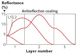
An ideal BBAR
To create a coating that operates over the broadest possible wavelength band, some simple design principles apply. If there were a substrate of index 4.0 such as germanium in the infrared spectral band, the square root equation indicates that the best QWOT AR coating layer would have an index of 2.0. And if two layers are used, their indices and thickness can be further optimized to give a broader AR band (see Fig. 3). This procedure can be extended to three, four, and five or more layers by following a step-down-index-vs.-thickness refractive index profile.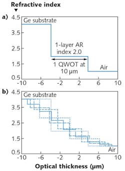
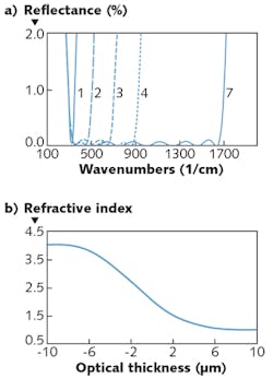
In the extreme case of an infinite number of layers, the index profile would have a Gaussian shape. The overall thickness of this ideal AR coating is slightly over two QWOTs at the longest wavelength or lowest frequency in the pass band (300 cm-1). The AR band of this ideal AR coating would extend from that longest wavelength to ALL shorter wavelengths!
Lithographically textured surfaces
With the rapid advance of lithographic techniques and the materials that can be etched, it is now possible to make mechanical surfaces whose textures/shapes create the index-vs.-thickness profiles on a microscopic scale that approximate those needed for very BBAR coatings. The individual features of such an etched surface must be less in height and width than the shortest wavelength in the desired AR band.
The ideal for an etched AR coating is a series of pyramids with curved slopes (see Fig. 5). Here, the average area ratio between the air (or vacuum) and substrate material at any given vertical level matches the previous step profile shown on the left side of Fig. 4. But in some applications, a pyramidal profile with straight edges can provide an adequate approximation of the ideal etched profile for some AR coating applications.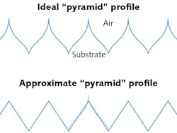
For a very broadband AR coating, the ideal profile of the index-of-refraction-vs.-thickness from a substrate to the media (usually air or vacuum) is a Gaussian-like curve starting from the index of the substrate and going to the index of the medium over a thickness/distance of approximately one half-wave optical thickness at the longest wavelength in the antireflection band. This can be approximated by simpler coatings of homogeneous index for narrower AR bands, and by lithographically etched substrates for some materials.
Finally, in some special cases where the AR band required is for only one wavelength (as in a laser), single- or double-layer AR coatings can work quite well.
REFERENCES
1. O. Smakula, "Verfahren zur Erhoehung der Lichtdurchlaessigkeit optischer Teile durch Erniedrigungdes Brechungsexponenten an den Grenzflaechen dieser optischen Teile," German patent DE685767 (C) (1935).
2. J. Strong, J. Opt. Soc. Am., 26, 1, 73–74 (1936).
3. R. R. Willey, Practical Design of Optical Thin Films, Fourth Edition, Sec. 2.10, Willey Optical, Consultants, Charlevoix, MI (2014).
About the Author

Ron Willey
Willey Optical Consultants
Ron Willey has more than 50 years experience as individual contributor and director of optical system and optical coating development, design, and production. He eaches short courses internationally, and is author of many technical papers and five books. Mr. Willey graduated from the Massachusetts Institute of Technology, having majored in optical instrumentation. He also earned a masters degree in computer science from the Florida Institute of Technology. He has taught optics at the Florida Institute of Technology, the University of Wisconsin, and Martin Marietta Corporation. He has taught optical thin film design, development, and production at SPIE, the Society of Vacuum Coaters, Florida Institute of Technology, and the University of Wisconsin.