Interferometry: Achieving precision radius metrology for large optics
BRUCE TRUAX
Fabrication of optics for semiconductor lithography, remote sensing, and other high-precision applications requires tight control of lens parameters, including surface figure and radius of curvature. Engineers working in these demanding applications must control uncertainty in their radius of curvature metrology well enough to ensure the success of the resulting processes.
The most accurate method for measuring radius of curvature is to use an interferometric radius slide, which combines a displacement-measuring interferometer with a Fizeau laser interferometer. The question is, is it good enough for the intended application?
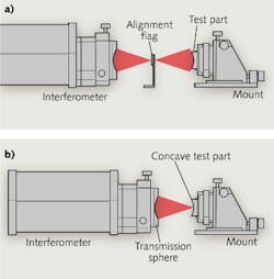
Two steps are followed when using a Fizeau interferometer to measure radius in a basic radius-of-curvature measurement configuration. First, the optic to be tested is aligned to the spherical beam from a transmission sphere to produce a null interference pattern (see Fig. 1a). When the interference pattern is nulled, the center of curvature of the part under test is precisely aligned with the center of curvature of the reference surface of the transmission sphere. This position is known as the confocal position.
The axial position of the mount supporting the surface under test is recorded, and then the mount is translated until a point on the surface of the part under test is located at the center of curvature of the reference surface of the transmission sphere (see Fig. 1b). This location is often referred to as cat's eye and results in a mirror-image reflection of the light striking the test part and a quasi-null interference pattern. The axial position of the support mount is recorded at the cat's eye position. The axial difference of the support mount between confocal and cat's eye is the radius of curvature of the surface under test.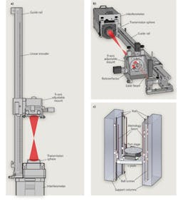
This concept is trivially simple, and yet the devil is in the details. If a measurement uncertainty of 0.01% is needed, the simple measurement described above can provide the desired results. But for high-precision optics, uncertainties of 0.01% (100 ppm) are inadequate. These users often want to achieve uncertainties one or two orders of magnitude better (1-10 ppm).
Achieving this level of precision requires eliminating or compensating for the three major sources of error. From largest to smallest, these are Abbe error, endpoint uncertainty, and stage-position uncertainty.
Abbe error
Accurate measurement of the precise amount of motion along the optical axis requires a well-designed mount and rail system for positioning the test part connected to a precision linear-displacement measuring device. A common method for measuring the z-axis motion of the part under test is to support the part in an adjustable mount, connected to a guide rail and an encoder read head (see Fig. 2a). The encoder head moves with the stage and reads the divisions on the encoder scale.
Conceptually this is a very simple setup, and works well for measurement precision of a few microns. The problem is that it is not possible to make the guide rail perfectly straight or the table perfectly flat. This causes some "wobble" in the mount, resulting in Abbe error (see Fig. 3).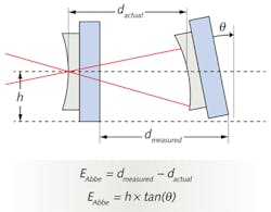
A simple example can point out the sensitivity of the radius measurement to the flatness of the table and the straightness of the rail. If we assume that the center line of the test part is approximately 100 mm above the table and we also assume that the feet under the mount are separated by 100 mm, then by simple geometry the Abbe error introduced is identical to the flatness of the table. A similar argument can be made for the straightness of the guide rail. A tolerance of 1–5 μm is reasonable for these errors.
When using a simple encoder scale, raising the scale to the height of the optical axis can reduce the Abbe error due to the table flatness, but it is still necessary to have a very straight guide rail with very accurate guides to minimize the error. Achieving an uncertainty of less than 1 μm proves to be very difficult using an encoder-based radius measuring solution.
To eliminate Abbe error completely, it is necessary to put the measurement axis coincident with the optical axis of the Fizeau interferometer. This can be achieved two different ways. The most common method is to place a retro-reflecting cube on the optical axis, behind the part under test, and to monitor the displacement of this cube using a displacement-measuring interferometer (DMI; see Fig. 2b).
This works quite well—the only drawback being that the air path for the stage-position measurement is longest for high-numerical-aperture (NA), short-radius optics. The long air path results in instability in the DMI measurement due to air turbulence. To minimize the uncertainty, averaging and good environmental control are required.
The second method to eliminate Abbe error is to place three retro-reflecting cubes around the part under test and use three DMIs to monitor the position of the stage in z, roll, and pitch (see Fig. 2c). The roll and pitch monitoring can be used to keep these degrees of freedom constant during translation, which further reduces measurement uncertainty. By placing the laser beams for the DMI on the same side of the test part as the transmission sphere, the uncertainty due to the index of refraction of air and variations in the environment are minimized for shorter part-radius measurements.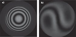
Endpoint uncertainty
Anyone who has used an interferometer to test spherical optics knows that adjusting the position of the part under test to exactly null the interference pattern can be difficult. This is particularly true for steep curves, where axial-position errors on the order of 1 μm are easily visible. Identifying the null position at cat's eye is even more difficult because the mirroring of the wavefront results in an interference pattern containing a considerable amount of coma (see Fig. 4).
The inability to perfectly null the two end points results in what is referred to as endpoint uncertainty. By using the interferometer to measure the residual spherical power at the two endpoints and knowing the ƒ-number of the measurement beam, the axial position error at each endpoint can be computed, and this uncertainty can be reduced to much less than 1 ppm.
Stage position metrology uncertainty
Both the linear encoder and DMI methods suffer from cosine error due to misalignment between the direction of travel of the stage and the displacement-measuring device. A misalignment of 1.4 mrad (4.9 arcmin) will result in an error of 1 ppm. In addition to cosine error, each method suffers from scale factor errors that are unique to their measurement technique.
Linear encoders can be purchased in various grades and use a variety of materials for the encoder. Steel tape scales typically have an uncertainty of ±5 to ±15 μm. In addition, they also have a thermal-expansion coefficient of approximately 10 ppm/K. This level of uncertainty is inadequate for precision radius metrology.
Better performance can be achieved using ceramic-glass scale encoders, which have an uncertainty in the range of ±1 μm and a low thermal-expansion coefficient. Ceramic-glass scale encoders are preferred for radius metrology, but are limited by Abbe errors.
The primary uncertainty of the DMI for radius measurements is the variation in the index of refraction of air with atmospheric conditions (temperature, pressure, and humidity). Since DMI technology uses the wavelength of the laser source as the ruler, knowledge of the wavelength is critical.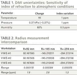
For a helium-neon (HeNe) laser-based DMI, the frequency of the laser line is known to much better than 1 ppm, so wavelength uncertainty is then determined by the uncertainty in the index of air. The wavelength of light in air is given by:
λair = c/nv
where c is the speed of light in a vacuum, n is the index of refraction of the medium, and v is the frequency of the laser line. Therefore, as n varies, there is a corresponding inverse change in the measurement scale.
The most commonly used equation for the refractive index of air is known as the Edlén equation,1 which is complex and must be handled correctly. NIST has created a website that makes computing the index of air quite simple; it can be found at http://emtoolbox.nist.gov/Wavelength/Edlen.asp. This website uses a modified version of the Edlén equation that has been updated for improved accuracy. Using this handy calculator, the environmental sensitivities are determined and shown in Table 1.
The values in this table highlight that knowledge of the temperature and pressure are critical to accurate measurements when using a DMI, while humidity is much less important.
It is also important to note that altitude can change pressure dramatically. While varying weather conditions often result in a change in pressure of a few percent, an increase in altitude of 1000 m results in a decrease in pressure of approximately 12%, resulting in a 33 ppm change in the index of air and a corresponding 33 ppm error in a radius measurement.
To compensate for the variation in the index of air, the Zygo radius-measurement software application allows the user to enter the current atmospheric conditions and then automatically scale the DMI measurements for the refractive index of air. Note that it is important to measure the temperature as close as possible to the DMI metrology cavity. Using temperature data that does not correspond to the DMI may introduce more uncertainty into the radius measurement.
Measurement results
In an example of putting the above principles into practice, Zygo recently manufactured a number of large vertical lens-measurement workstations, which implemented radius metrology using a three-beam system with Zygo's ZMI 2000 displacement measuring interferometers (see Fig. 2c). An important feature of these systems is the ability to measure radius of curvature with unparalleled uncertainty.
Each workstation was characterized for radius repeatability and then inter-compared to characterize radius uncertainty. Repeatability tests were performed over a 1 h period on each instrument using Zygo MetroPro software's automated radius-measurement capability. Each system demonstrated a radius repeatability of better than 100 nm (~1.5 ppm) on a 60-mm-radius, convex Zerodur sample.
After installation at the customer's facility, an inter-comparison of the Zygo workstations was performed. The customer used unique transmission spheres to measure common samples in each of the three workstations. The transmission spheres ranged in ƒ-number from ƒ/1.2 to ƒ/1.6, with input apertures between 100 and 300 mm. Careful measurement procedures were followed to ensure that the temperature, humidity, and pressure were entered into the MetroPro radius software application. The results in Table 2 demonstrate correlation between the three systems of better than 3 ppm.
Precision optical systems are driving the requirement for higher-accuracy radius of curvature metrology of spherical optics. Achieving the lowest level of uncertainty requires a stage metrology system based on DMI. Using a properly designed DMI-based radius scale, combined with environmental correction and the proper test procedure, it is possible to measure radius with uncertainties of better than 3 ppm.
REFERENCE
1. B. Edlén, JOSA, 43, 5, 339–344 (1953); http://dx.doi.org/10.1364/JOSA.43.000339.
Bruce Truax is manager – Engineering Special Projects at Zygo Corporation, Laurel Brook Road, Middlefield, CT 06455; e-mail: [email protected]; www.zygo.com.