FIBER FOR FIBER LASERS: Matching active and passive fibers improves fiber laser performance

In this article, we review some of the methods used to match fibers and discuss how measurements play an important role in the manufacturing of matched fibers. We also show how matched fibers can improve overall laser performance, enabling singlemode beam quality at high powers. Finally, we present the methodology and results of matching active and passive fibers and discuss the key measurements necessary for fiber matching.
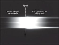
Advances in fiber technology are a key factor in fiber lasers operating at high power levels. These fibers are most commonly based on the double-clad fiber geometry, commonly with an octagon-shaped inner cladding to increase pump absorption (see Fig. 1). More recent improvements in the fiber technology include the optimization of the glass composition to eliminate photo-darkening and improvements to the low-index polymer coating used in double-clad fibers to form the pump waveguide.
Together these steps enable commercially available double-clad fibers that operate reliably at the 1 kW power level without degradation of the singlemode beam quality while maintaining lifetimes in line with industrial laser standards. A more recent challenge has been sustaining this performance at the multikilowatt level.
A typical kilowatt-level fiber laser is based on a large-mode-area (LMA) Yb-doped double-clad fiber, pumped by multiple laser diodes and operating either in a grating-based laser oscillator or a master oscillator power amplifier (MOPA) architecture with the LMA fiber deployed in the amplifier stage. In either case, a series of passive-to-active (Yb-doped) fibers are spliced to form a monolithic chain of fiber components (gratings, couplers, passive delivery fiber). Industry-standard Yb-doped LMA fiber is a 20/400 design, based on a 20-µm-diameter, low-NA core (0.065, typically) with a 400-µm-diameter shaped inner cladding for the pump waveguide.
The challenge has been to operate this chain of fibers and components at the multikilowatt power level without deteriorating the output beam quality, while maintaining the required level of system reliability. In particular, there have been reports on the tendency of higher orders in the LMA core to propagate and deteriorate the beam quality at high power levels above 1 kW.
To achieve high powers reliably and repeatedly, the fiber components within the fiber laser need to be carefully matched, beyond the tolerances of the previous generation of LMA fiber technology. With the correct selection and matching of the entire chain of active and passive fibers, we have demonstrated a stable singlemode beam from the latest generation of commercially available matched double-clad LMA fibers at the 2 kW output power while maintaining singlemode beam quality.
Matching active and passive fibers
In a double-clad fiber there are two waveguides: the Yb-doped core that forms the signal waveguide and the inner cladding waveguide for the pump light. The inner cladding of active fiber is often shaped to scramble the cladding modes and increase pump overlap with the doped core.
The matching of active and passive fibers for improved signal integrity requires optimization of the core/clad concentricity, and the mode field diameter (MFD) through the core diameter and NA, which reduces splice loss. This is primarily done by tightening all of the pertinent fiber specifications.
Matching fibers for improved pump coupling requires optimization of the clad diameter for both the passive and the active fiber. To maximize the amount of pump power coupled into the active fiber, the active fiber is designed with a slightly larger clad diameter than the passive fibers delivering the pump power. As an example, passive fibers with clad diameters of 395 µm spliced to active octagon-shaped fiber with clad diameters of 400 µm improve the coupling of the pump power into the active fiber (see Fig. 2). Note the increase in the cladding diameter at the splice of the passive fiber to the active fiber.
The matching of active and passive fibers can be optimized in several ways. The easiest method for matching the signal carrying light is to have identical NA and core diameters for each fiber. However, this does not account for all the refractive-index profile features. Matching of the MFD is also a method used to create matched signal carrying fibers.
We found matching all three of these components provides the best set of fibers to build high-power amplifiers and lasers. Essentially, the MFD is modeled and the resulting target NA and core diameter are developed. The core-rod is made and before being drawn into fiber its core diameter and NA are checked. Based on the refractive index measurements, the final core/clad ratio is determined and adjusted to the target MFD.
This approach accounts for details of the refractive index profile, which can be measured easily and with high accuracy on the preform, before it is drawn into fiber. The splice loss (as a percent of total power) vs. different MFD specifications based on modeling results can be shown (see Fig. 3). It demonstrates when the MFD specification is larger (15.76 to 20.4 µm)—typical of unmatched fibers—the splice loss due to MFD mismatch can be much greater than matched fibers with tighter MFD specifications. The shaded area is an example of splice loss for precision matched fibers where the MFD specification is much tighter (16 to 18.5 µm).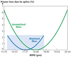
In addition to the parameters described above, other optical and geometrical parameters have been tightened in matched fibers. Through processing improvements and tighter control of the core NA, the spectral core attenuations and the bending loss have been reduced. The core/clad offset of these fibers has also been minimized, making splicing of the active and passive fibers more repeatable and easier. Additionally, tightening of the cladding and coating diameters has further reduced variation and created a more reliable product.
Testing and measurement for matched fibers
Accurate testing and measurement, and a reproducible and repeatable manufacturing process are vital to providing well-matched LMA fibers. The key parameters that need to be measured for feedback and process control are NA, core and clad diameter, core/clad offset, MFD, and core and cladding attenuation.
Only fibers meeting specific matching requirements are sold as matched sets, having first satisfied our criteria for repeatability and yield as demanded in high-volume manufacturing. Testing is done on both commercially available benches and home-built machines.
Spectral core attenuation and cladding attenuations are measured on commercially available metrology equipment. To effectively measure the core background losses in LMA fibers, a high-order mode filter consisting of approximately 100-mm-diameter loop is necessary. Using loops larger than 100 mm diameter will cause the higher-order modes to skew the results. Conversely, placing the fiber in a smaller-diameter loop would significantly increase the fundamental mode macrobending losses, increasing measurement noise in the higher wavelength region.
Measuring the core background attenuation also requires an effective cladding mode stripper. One effective method to remove cladding mode power is to replace the fiber coating on both fiber ends with index matching fluid.
Two important parameters to control for optimal fiber matching are the core and clad geometries, especially the core/clad offset. A fiber geometry bench capable of measuring a wide range of fiber diameters that offers exceptional repeatability is necessary to best match active and passive fibers.
There are limited commercial measurement devices available, but developing a home-built bench capable of measuring larger clad fibers repeatedly is feasible. The table shows the standard deviations of a home-built bench and two commercially available benches (Bench A and Bench B). All of these benches are capable of measuring the core and clad diameters, core and clad noncircularity, and the core/clad offset.

The home-built bench was designed and functions based on the principles of FOTP-176. It is important the repeatability be superior to best match active and passive fibers. Based on the standard deviations reported in the table, the repeatability of the home-built bench is better than the commercial benches.
We believe the core diameter variation caused by measurement is primarily related to variations in the modal power distribution of the light source. Uniform core illumination must be used to reduce the modal power distribution, both spatially and angularly. Nonuniform core illumination causes some modes of the few-moded LMA fibers to become the dominant modes. Therefore, if the source NA is unstable and illuminates the core differently each time, then the modal power distribution in the fiber core will change. Consequently, the intensity profile of the core will change, which changes the measured core diameter value.
We found one way to stabilize the core diameter measurement is to fix the launch NA and launch spot size. Equally illuminated step index fiber is used to deliver the light from the source to the fiber under test.
The other improvement in the home-built bench was reducing the wavelength of the illumination. The wavelength of the source was decreased from 850 nm to 530 nm. Decreasing the wavelength of the source light introduces more modes into the core and helps stabilize the mode power distribution and intensity profile of the core, improving the core geometry measurement performance. Using these techniques reduced the core diameter standard deviation by a factor of 1.7 compared to commercially available benches.
Test results
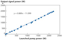
As a demonstration of the laser performance improvement using matched fibers, a power efficiency curve is shown in Fig. 4 for a 2 kW co-pumped fiber MOPA system using matched 20/400 LMA fibers. The efficiency is around 89% and a similar laser system using unmatched fibers would have higher splice losses, lower efficiency, and not provide a singlemode beam at power levels greater than 1 kW because of the presence of higher-order modes.
High-power double-clad fibers are commercially available that operate at the 2 kW power levels. Precision matched LMA double-clad passive and active fibers are now becoming available and improve laser performance by reducing the loss, confining the light better, and providing good beam quality at high operating powers. Such improvements further enhance the capabilities of fiber laser technology and have facilitated the growth of high-power fiber lasers. In coming years, as precision-matched fibers continuously improve and become more available, fiber lasers operating above 10 kW will become readily available.
REFERENCES
1. FOTP-176 - IEC 60793-1-20 Optical Fibres Part 1-20: Measurement Methods and Test Procedures - Fibre Geometry (ANSI/TIA-455-176-A-2003).
2. FOTP-78 - IEC 60793-1-40 Optical Fibres Part 1-40: Measurement Methods and Text Procedures - Attenuation (ANSI/TIA-455-78-B-2002).
About the Author
George Oulundsen
George Oulundsen is senior director and general manager at Coherent Corp.
Kevin Farley
Kevin Farley is a scientist at Nufern.
Jaroslaw Abramczyk
Jaroslaw Abramczyk is technical manager–fiber test and measurement at Nufern.
Kanxian Wei
Kanxian Wei is senior scientist–research & development at Nufern.