LOW-LIGHT IMAGING: ICCD, EMCCD, and sCMOS compete in low-light imaging

MICHAEL P. BUCHIN
Call it image intensification or light amplification; either way, photon/electron multiplication is one of the core concepts behind modern low-light imaging technology. The development of night-vision capability was funded and driven by the needs of the military during World War II and the Korean War. Charge-coupled device (CCD) imagers arrived on the scene in the 1970s, evolved over the next three decades to become the sensor of choice for many astronomical, life science, and surveillance applications requiring extremely high resolution and/or hyperextended exposure times, and are only now being challenged as the workhorse of the consumer imaging market by the latest complementary metal-oxide semiconductor (CMOS) technology.1
Electron-multiplying CCDs (EMCCDs) were proposed and developed in the mid 1990s, with most of the funding support again derived from anticipated use in military and security imaging applications where moonlight and even starlight could provide sufficient illumination.
Scientific CMOS (sCMOS) is one of the newest sensor technologies to spin out of military programs. Rigorous testing for prototype small array samples took place in 2007/2008 and a full white paper release describing 5-Mpixel sCMOS sensors was published in the summer of 2009.2 Ever since it developed the very first night-vision goggles, the US Military has claimed unequivocally that “We Own the Night” and continues to invest in low-light sensor development to ensure that it never utters the words “We Share the Night.” This investment should continue to pay dividends into nonmilitary markets as limit-of-detection imaging expands into new applications.
Darker than night
This year, at least two low-light imaging review articles in major publications compared the first commercially available sCMOS products—Andor (Belfast, Northern Ireland) Neo and PCO (Kelheim, Germany) Edge—with CCD and EMCCD technologies.3,4 Although intensified CCD (ICCD) cameras have been shown to compare favorably to EMCCDs in the single-photon domain, none of these articles brings that data into discussion.5 Regardless of the pros and cons within each article, there is common ground when it comes to the characteristics of the ideal low-light detector: It should have the best combination of high quantum efficiency (QE) within the spectral band of interest; minimal or zero effective readout noise, dark counts, and dark current; high resolution and wide dynamic range; the ability to run at high speeds for dynamic event capture; and the ability to acquire the dimmest targets over extremely long exposure times.
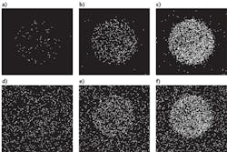
The Stanford Photonics Mega-10Z and Turbo/Z ICCD cameras, first introduced in 2004, were developed to meet most if not all of these criteria.6 Our experience with gallium-arsenide-phosphide (GaAsP) image-intensifier tubes in the mid 1990s gave us an appreciation for the high intrinsic QE and low dark counts of this photocathode material. Adding Peltier cooling (-20ºC nominal) and dual microchannel plates (MCPs) with direct fiber-optic coupling to scientific-grade CCDs creates unprecedented image quality for long-exposure bioluminescent imaging applications.7,8 Images that compare the cooled ICCD with a deep-cooled EMCCD show a noticeably better limit of detection with the ICCD for objects producing single-digit photon levels at the image plane (see Fig. 1).
Why ICCDs?
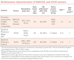
The superior light-detection limit of the cooled-cathode ICCD can be explained in part by comparing key performance data; note that sCMOS is not included as it cannot, in present embodiments, reach the same low levels of detection (see table). Once corrected for ENF (multiplicative noise), the QE of a back-thinned EMCCD is reduced by a factor of two to an effective level comparable to that of the GaAsP photocathode: 40–50% across the visible spectrum. Both cameras claim zero read noise and zero dark current contribution in the high-gain modes: the ICCD as a result of high photon gain ahead of the CCD/image formation and read-noise thresholding; the EMCCD via electron multiplication gain—so far, comparable. The cooled-cathode ICCD has 25–50 dark counts per frame per second (fps) or 1–2 counts on average at 30 fps. Clock-induced charge (CIC), which appears as a signal equivalent to a single-photon event, can typically result in a 1000–1500 per frame dark count equivalent at 30 fps in the EMCCD image.9 This several-orders-of-magnitude differential in ultimate noise floor (dark count and CIC) separates the cooled ICCD from the deep-cooled EMCCD when it comes to limit of detection. The Turbo-Z ICCD performs like a cooled single-photon-counting photomultiplier tube (PMT) consisting of a 300,000 pixel image plane with virtually no read noise or dark counts per 33 ms exposure.
Arguments against using the ICCD are 1) saturation of pixels at high gains in the presence of average photon flux levels greater than 2–10 per frame; 2) nonuniform gain for each single-photon event due to the MCP multiplying process as a noise source; and 3) reduced resolution from the intrinsic limit of the CCD due to point-spread “blur” in the intensifier tube output.
To address these drawbacks, we take advantage of speed and single-photon counting methods to recover dynamic range, signal to noise, and resolution. Since most single-photon imaging systems rely on slow clock speeds/long readout intervals to reduce read noise, it is counter-intuitive to think that faster is better for limit-of-detection imaging, but going faster means few photons per pixel per frame; at some point in the speed/flux window, pixels come out of saturation. The Turbo-Z ICCD runs 640 × 480 at 120 fps and 320 × 220 at 400 fps with 2 × 2 binning—again, with CCD read noise thresholded, resulting in zero electronics noise contribution to the data. Even with light gains of 100,000 and higher, dynamic range spanning one to hundreds of photons per pixel per frame can be achieved via photon accumulation imaging. Here, each pixel value is summed in image memory in real time or in playback/post process to create well capacity limited only by memory depth and collection time. Pixels are summed in grayscale or in vector domain (x-y address and count processed in “list mode”).
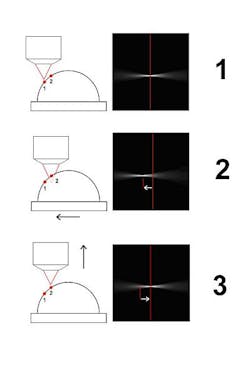
Dynamic range is further extended by going to even higher speeds and/or deeper frame accumulations. Single-photon detection processing can be applied to our images to eliminate amplitude variance and, through centroid processing, to collapse point spreads down to single and subpixel levels. Pixels can be expanded (binned) or compressed to fit the data/image processing requirements (see Fig. 2).Today, these operations, as well as real-time removal of cosmic ray events from each image before recording and/or accumulation, are performed in real time in Windows 7 and XP for 640 × 480, 16 bit, 120 fps images from the Turbo-Z using our proprietary Piper Control image acquisition software. Higher speeds and faster processing times are anticipated in future versions.
Risky? Not so much
Historically, image intensifier tubes have been noted to be susceptible to damage from overexposure to high light levels. Since the input photocathode is more or less identical to a PMT, there is risk. That risk, however, is mitigated by using active photocathode gating. Stanford Photonics uses autogating methods developed and optimized over the past 20 years for military night vision, daylight-to-starlight imaging in all our scientific products and we are in the process of adding redundant dynamic cathode protection to Piper. Our exclusive ABF/Automatic Brightfield has shown great efficacy in tube protection over its years in service. Using gating power supplies as standard components in our products allows them to be used in other applications, such as imaging of lanthanides and other time-resolved luminescent probes.10
To complete the picture, it is important to include one more technology with similar advantages to the cooled ICCD. Some image-photon-detectors (IPDs) also use MCP amplification and cathode cooling to get near-zero dark-count levels with single event time resolution on the order of a few nanoseconds. However, such detectors require dedicated readout amplifiers that can only process one event at a time and typically have a dead time on the order of a few microseconds. Without a massively parallel electronic readout, this dead time limits the maximum light level that can be imaged by such detectors to a few-hundred-thousand photons per second over the cathode area, preventing their use for high-flux grayscale imaging. An ICCD detector can be used at high flux levels by reducing gain and/or by using photocathode gating. Nevertheless, the IPD can provide spectacular results when photon counts per pixel are in the single digits.11
It is important to consider that there will be further evolution of EMCCD and sCMOS-based cameras, but at present, our tests as well as those performed by independent evaluators show a quantifiable advantage in limit-of-detection imaging using our ICCD technology.12, 13 Currently, sCMOS looks like it could become the next best thing for more generalized low-light imaging if one considers the combination of speed, dynamic range, and resolution as well as probable improvements in signal to noise on the horizon. And it will be interesting to see where EMCCDs fall once sCMOS finds its way into more applications. Last but not least, it is important to remember that it is cheaper to make light than it is to detect it. In the past several years, light-emitting diodes (LEDs) have become less expensive while advancing in terms of brightness and spectral offerings. So let’s not overlook the fact that the venerable CCD can produce excellent images when used in tandem with good illumination—intelligently applied. Today, cooled CCD cameras that used to cost in the $15–$25K range can now be purchased for under $5K, making this technology accessible to the backyard astronomer searching the vast void of blackness between the points of light that compose the constellations in the night sky.
REFERENCES
1. www.dpreview.com/news/0908/09080601sonycmos.asp.
2. C. Coates, B. Fowler, and G. Holst, “sCMOS, Scientific CMOS Technology, A High-Performance Imaging Breakthrough,” Andor White Paper, www.scmos.com/downloads/ (2009).
3. C. Coates and C. Campillo, Laser Focus World, 47, 3, 40–45 (March 2011).
4. J.R. Joubert and D.K. Sharma, Photonics Spectra, 45, 3, 46–50 (March 2011).
5. D. Dussault and P. Hoess, Laser Focus World, 40, 9, 69–75 (September 2004).
6. N.D. Lamontagne, Biophoton. Intl., 11, 1, 38–45 (January 2004).
7. www.plosone.org/article/info%3Adoi%2F10.1371%2Fjournal.pone.0015869.
8. L. Marpegan et al., “Circadian Regulation of ATP Release in Astrocytes,” submitted for publication to J. Neurosci. (2011).
9. http://bit.ly/l012Bf and http://bit.ly/ieyjdP (Spectra Services and Princeton Instruments documentation)
10. N. Gahlaut and L.W. Miller, Cytometry Part A, 77A, 1113–1125 (2010).
11. J.-R. Martin et al., PLoS ONE online, Issue 3, e275, 1–8 (March 2007); www.plosone.org/article/info%3Adoi%2F10.1371%2Fjournal.pone.0015869.
12. S. Miller, “Attomole Detection of BRET-Qdot Nanoprobe,” Zymera Inc. internal white paper (Sept. 16, 2010).
13. E. Karplus, “Direct comparison of single photon imaging performance using cooled GaAsP ICCD and cooled, back-illuminated EMCCD,” internal communication, available from Science Wares Inc. (2011).
Michael P. Buchin is president of Stanford Photonics Inc. (SPi), 1032 Elwell Court, Suite 104, Palo Alto, CA 94303; e-mail: [email protected]; www.stanfordphotonics.com.

