FIBERS FOR TELECOMMUNICATIONS: Can standard fibers perform in next-gen coherent communications systems?
RONG CHEN, CHARLES WARD, SERGE ASSELIN, MAURICE O'SULLIVAN, and MICHEL BELANGER
Recently, dense wavelength-division multiplexing (DWDM)-based communications systems using digital signal-processing (DSP)-assisted coherent detection have been made commercially available.1 Coherent systems offer increased capacity and spectral efficiency while preserving optical reach and agility on the existing fiber plant.2 However, the question of optimizing optical fiber design to address coherent system requirements has not been widely explored. A review of the main characteristics of coherent transmission systems and commercially available fibers shows that–not unlike standard communications networks–optical fibers with low loss, large effective area, and high local chromatic dispersion are preferred for optimizing coherent system performance.
Defining coherent communications
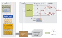
A coherent optical transport system (OTS) is composed of eighty 100 Gbit/s (100G) modems operating on a 50 GHz C-band (1525-1570 nm) optical line system (see Fig. 1). The modem has a 25 Gbaud two-polarization quadrature phase-shift keying (QPSK) modulator and the transmitter contains two I-Q ("I" represents the in-phase component and "Q" represents the quadrature component) modulators–one per polarization.3 Each modulator acts on one of two orthogonal, optical polarizations that are later combined in a polarization beam combiner. In the coherent receiver, the incoming signal is first split by polarization and then mixed with a local oscillator at a frequency near that of the transmitter. The resulting mixing products are digitized and processed by a DSP CMOS application-specific integrated circuit (ASIC).
The 100G modem utilizes the phase of the signal to carry information; therefore, the receiver needs to preserve this information through the optical-to-electrical conversion. To perform this operation, a coherent receiver is required–a type of receiver that produces electrical signals that are proportional to the phase of the incoming optical signals. Compared to more conventional receivers used in intensity modulation-based communications systems, this receiver allows the use of more parameters to convey data and also allows improved receiver sensitivity–two fundamental characteristics essential for high-data-rate modems. Using more parameters to convey data means that the modem can be operated at a lower frequency (lower baud rate), making it easier to manufacture and test. The modem can also be manufactured using less costly components and making the resulting optical signal less sensitive to impairments that affect higher-baud-rate modems. Since this type of receiver is called "coherent," the whole transmission system is termed coherent as well.
The key element of the coherent system is the receiver CMOS DSP ASIC. This device must perform, in real time, all the required mathematical processes to track and retrieve the incoming phase and polarization state of the signal; must compensate for impairments such as polarization mode dispersion (PMD) and chromatic dispersion (CD); and, finally, perform carrier and data recovery.
Coherent system performance benefits are significant. In addition to enabling phase and polarization state as two light parameters suitable to carrying information, PMD and CD are compensated electrically using digital filters, thus avoiding the costly deployment of optical compensators at every optical line amplifier.4 This improves the economics of the system and ensures its operational ease.
We will assume that the modems are also equipped with high-gain forward-error correction (FEC), allowing correction of system bit-error rate from 3 × 10⁻³ to better than 1 × 10-15 (>9 dB of coding gain). Forward-error correction is a method for detecting and correcting incoming errors from an imperfect transmission signal by using extra bits of transmitted information. We will assume the amount of extra transmitted bits adds 7% overhead (additional signal) to the transmission. The optical system is composed of a chain of C-band erbium-doped fiber amplifiers. Dynamic 50 GHz gain-flattening filters are deployed as needed at approximately every six to eight spans.
| Range of fiber parameters under consideration for coherent communication | ||
| Parameter | Min | Max |
| Chromatic dispersion (ps/nm/km) | 10 | 32 |
| Loss (dB/km) | 0.15 | 0.25 |
| Effective area (μm2) | 50 | 160 |
Performance of current fiber designs
Before exploring various optical fiber designs and their impact on coherent system performance, the impact of commercial fiber designs on 100G QPSK systems should be quantified. We examined the system performance (reach) of three G.652 fibers (designated G.652 as per the International Telecommunication Union or ITU standard; see www.itu.int) with different loss parameters and three G.655 fibers with different dispersion and loss parameters. Basically, G.652 fibers have a higher chromatic dispersion, larger effective area, and somewhat lower loss than G.655 fibers. For all simulation results, the system conditions (such as the in-fiber power per wavelength) were always adjusted to obtain best system performances.
A plot of the reach penalty versus the percentage of in-line chromatic dispersion left in the fiber shows that 0% in-line dispersion implies that no dispersion-compensation module (DCM) is used in the line while 100% in-line dispersion implies that every span is perfectly compensated (see Fig. 2). After normalizing the results to the fiber allowing the longest reach, it is clear that the performance of G.652 optical fibers is better than that of G.655 fibers: the average reach allowed by G.655 fibers is about 55% of the average reach of the G.652 fibers. This is a significant performance gap. The main reasons for this gap are as follows: smaller noise accumulation; reduced nonlinear effect; and, to a lesser extent, high local dispersion.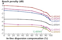
Because the average attenuation of G.652 fiber is approximately 15% lower than that of G.655 fiber, the noise accumulation is limited and thus longer reach can be achieved. However, this is not sufficient to account for the wide performance gap. The next main reason for the gap is the reduction of nonlinear effects enabled by the larger effective area of G.652 fiber over that of G.655 fiber. Nonlinear effects such as cross-phase modulation perturb the receiver phase tracking required in QPSK systems and are of particular concern. These effects are reduced in G.652 fiber compared to G.655 fiber.
Another important characteristic is that in all cases (for all fibers), the best results are obtained when no in-line DCM is present and dispersion compensation is performed in the terminal. Using coherent transmission with modems equipped with a coherent receiver, CD can be compensated at the terminal in the electrical domain using DSP. For all commercial fibers considered here, the second G.652 fiber (fiber #2) provides the best performance. Following the previous points, this fiber has a typical G.652 effective area (approximately 80 μm2) and the lowest loss among all the G.652 fibers at 0.17 dB/km–making its reach about 20% better.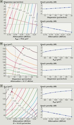
Beyond standard fibers
With these standard fiber results in mind, a more detailed exploration of fiber parameters is proposed (see table). Using a broad range of performance limits for optical fiber chromatic dispersion, optical loss, and effective area (in some cases, broader than what can be manufactured using commercial fiber fabrication methods), coherent system performance can be examined as these parameters are varied. The goal is to explore coherent system impact of various fiber designs–even if those designs have wider-than-practical parameters.
Based on the analysis of standard fiber types in the previous section, the dispersion mitigation will be in-terminal only, as it was shown to be the optimum compensation scheme. All performance results (reach penalty) are made in reference to that of the G.652 fiber #2 described previously. To better understand the impact of different fiber parameters on coherent system performance, the reach penalty is presented graphically in an equal-penalty contour plot when two fiber parameters are varied.
Analysis of equal-penalty contours for the joint impact of dispersion/attenuation, effective area/dispersion, and effective area/attenuation, respectively, show that just like standard fiber designs, the main fiber parameters governing system performance are attenuation and effective area (see Fig. 3). Over the range of fiber parameters investigated, system performance improves by more than 250% as fiber loss varies from 0.25 dB/km to 0.15 dB/km, and by 200% as effective area increases from 50 μm2 to 160 μm2. Much less improvement is observed as the dispersion parameter is increased from 10 ps/nm/km to 32 ps/nm/km.
It is interesting to observe that, within the range considered, the fiber loss can be reduced without causing significant additional nonlinear effects due to increased effective length. In summary, our analysis indicates that the best fiber design for coherent communications systems is the one that minimizes fiber loss and has the largest effective area. And yet, within the range of fiber parameters considered, no optimum performance point was observed. In order to determine this optimum point, the scope of this work would need to be broadened and include an assessment of fiber cost increases required to achieve the desired parameters.
REFERENCES
1. K. Roberts et al., IEEE J. Lightwave Technol. 27, 16, 3546-3559 (August 2009).
2. K. Roberts et al., "40 Gb/s optical systems with electronic signal processing," Proc. Lasers and Electro-Optics Society (LEOS), paper WFF4, 688-689 (2007).
3. E. Ip et al., Optics Exp. 16, 2, 753-791 (January 2008).
4. M.G. Taylor, IEEE Photon. Technol. Lett. 16, 2, 674-676 (February 2004).
Rong Chen, Charles Ward, and Serge Asselin are members of the scientific staff and Maurice O'Sullivan and Michel Belanger are senior members of the scientific staff at Ciena, Carling Campus, 3500 Carling Ave., Ottawa, ON, K2H 8E9, Canada; e-mail: [email protected]; www.ciena.com.