OPTOELECTRONIC APPLICATIONS: OPTICAL TOOLS - Trapping with light ...fantastic
First discovered in the 1970s by Arthur Ashkin at Bell Laboratories and further developed by physicists and biologists worldwide in the 1980s and 1990s (many of whom went on to win Nobel Prizes based on their work), optical trapping has become a well-respected research tool for single-molecule and force-measurement studies (see “How optical trapping works”).1 In recent years, its unique ability to measure the position of a specimen or particle while a force is being exerted on it-combined with the push to study cellular and molecular processes at increasingly precise scales-has prompted new interest in optical trapping, particularly for biophysics and materials-science applications.
“It has become possible to use a number of techniques-FRET, trapping, fluorescence, atomic-force microscopy, and magnetic tweezers, for instance-to isolate and study one molecule or nucleic acid at a time,” said Steven Block, professor of applied physics and biological sciences at Stanford University (Stanford, CA) and a pioneer in the field of optical trapping. “Optical tweezers have the advantage of being able to apply controlled forces and controlled torques to biological elements.”
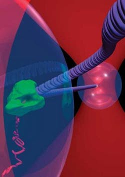
Last February, for example, Block’s group used infrared light to trap and map the motion of RNA polymerase at 1 Å resolution, an important advance in the study of protein mechanics (see Fig. 1).2 These experiments utilized a custom-built optical-trapping system with a diode-pumped solid-state laser (532 or 1064 nm) housed in a separate sound-proof room from the power supply, which eliminates the need for cooling and vibration control, resulting in a very stable beam-paramount when trying to measure atoms, Block notes.
There have been advances outside of biology as well. In March 2007 researchers at Argonne National Laboratory (Argonne, IL) reported success in laser cooling and trapping atoms of radium, the first time this rare element has been captured in a magneto-optical trap (MOT) and the first time room-temperature blackbody radiation played a role in keeping the atoms trapped.3 This advance has implications for studies of time-reversal violation and related matter/antimatter theories, according to Jeffrey Guest of the Argonne Physics Division. In their experiments, Guest and his colleagues used 100 to 200 mW of power from a 714 nm Ti:sapphire ring laser to cool the radium atoms and slow them down. Repumping—which increases the amount of time the atom remains in the slower state, according to Guest—was done using a 1429 nm external-cavity diode laser locked to a Fabry-Perot cavity stabilized by a HeNe laser. The blackbody radiation served as a second repumping source. The atoms were captured with magnetic fields and laser beams tuned near the atoms’ resonant frequency.
“With an atom as complicated and heavy as radium, which has no stable isotopes, you need to scatter tens of thousands of photons off the atom to slow it down because the momentum of the photons is so much slower and the sample size is so small,” Guest said. “The repumping makes a difference in the atom sticking around for seconds versus milliseconds.”
New traps, new techniques
Despite the advent of commercial 3-D piezoelectric stages with capacitive sensors, stage-based force-clamping techniques, high-bandwidth position detectors, and increasing interest in optical trapping for applied research and biophysics, commercialization has been limited primarily by the cost of the technology as the complexity of the applications and experiments increases. There are optical-trapping systems on the market, such as the MicroBeam and MicroTweezers systems from P.A.L.M. Microlaser (Bernreid, Germany) and the BioRyx 200 from Arryx (Chicago, IL)—one of the pioneers in this field, Cell Robotics, is no longer in business, although the company retains a large intellectual-property portfolio related to optical trapping-but most of the systems in use today are “home grown,” according to Block.
“You need extreme stability and the ability to measure very tiny positions, and there is no company making an optical trap that is capable of making a very fine measurement of the trap,” Block said.
While a simple single-beam optical trap can be created from off-the-shelf parts for a few thousands dollars, the abilities of such systems are limited. Increasing their capabilities increases the cost; some custom-built systems can contain entire subsystems devoted just to position detection, plus multiple light sources—one for trapping, another for position detection, a couple for fluorescence detection, and a mercury arc lamp for illumination, according to Block. To achieve what Block’s group has done, for example, requires a combination of custom optics, piezoelectric stages, and computer-controlled solid-state lasers-at a cost topping six figures.
But commercial developers say this scenario is beginning to change. According to Joe Plewa, vice president of research and product development at Arryx, a company commercializing holographic trapping technologies originally licensed from the University of Chicago, optical trapping is on the verge of evolving from a very successful research platform into a standard experiment tool for applied research in a number of fields.
“Optical trapping provides the ability to isolate, manipulate, and separate, so why hasn’t it taken off?” he said. “People aren’t using trapping for certain types of experiments or measurements because of hitches on the imaging side, the software side, and the sample delivery side. But I think this is changing.”
Arryx is hoping its holographic-optical-trapping (HOT) technology, which uses focused light to form optical traps that can hold, move, rotate, join, separate, stretch, and otherwise manipulate hundreds of microscopic and nanoscopic objects, will be at the forefront of this evolution. In fact, the company is developing a complete force-measurement device to address the gap in commercial tools noted by Block and others. At the core of Arryx’s approach is the notion that if a single tightly focused beam of light can create a single optical tweezer, then N beams can create N simultaneous traps. Holographic optical trapping uses spatial-light modulators (SLMs) to split a single laser beam into up to 200 beams, each of which is relayed to a strongly converging objective lens and focused into a distinct optical trap (see Fig. 2).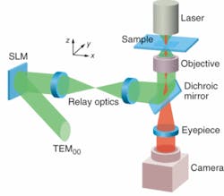
“You can use the hologram to create multiple traps that can be independently steered, you can place each trap wherever you want in a 2-D space and shift it wherever you want in the third dimension, and you can update the details at roughly 30 Hz for real-time manipulation,” Plewa said. “If you do optical trapping with some of the time-sharing techniques, such as with a galvonometer or acousto-optical detector, you tend to be confined to a 2-D focal plane and you can only scale up to five or ten traps. Because the SLM is a holographic device, you can do all sorts of other interesting things as well, such as vortex and ring-mode trapping, which opens up all kinds of new applications.”
Having recognized that the trapping mechanism is just part of a more-complex system comprising hardware and software for imaging, sample delivery, force measurement, analysis, and image processing, Arryx is taking a different approach to packaging and marketing its technology that could make optical trapping more attractive to a broader range of customers. The company is developing all of the components of an optical trapping system and making them available in an integrated but modular way that enables customers to build a system tailored to their needs and with “point and shoot” capabilities.
“Optical trapping holds promise to be a robust, powerful, and easy-to-use technique, used extensively throughout the sciences; however, adoption is currently limited by technical challenges for home-built systems and a lack of complete commercial solutions,” said Dan Mueth, chief technology officer at Arryx.
Other groups are focusing on reducing the costs associated with optical trapping by using less-expensive components without sacrificing resolution or throughput. Researchers in Ming Wu’s group at the University of California, Berkeley (Berkeley, CA) have developed optical tweezers that use optoelectronics, rather than lasers, as the energy source (see Fig. 3). According to Aaron Ohta, a graduate student in Wu’s group, the key difference is that optoelectronic tweezers use optical energy to create electric forces in prescribed places, rather than mechanical forces that can push things around. Ohta says this approach uses much less power than optical tweezers and the light does not need to be as carefully focused, helping to make the technique easier to implement for applications ranging from manipulating nanorods in the building of 3-D circuitry to manipulating cells with micron-level precision.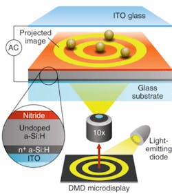
Using a couple of milliwatts of energy from an incoherent light source (an LED or halogen lamp) and a digital micromirror spatial-light modulator, Wu’s group has demonstrated parallel manipulation of 15,000 optical traps on a 1.3 × 1.0 mm2 area.4 More recently, the group reported the use of locally controlled electric fields to manipulate the positions of silicon nanorods or nanowires (100 nm in diameter and 1 to 50 µm long) at velocities of 20 µm/s.
“Our approach brings a dynamically programmable trap array that is controlled optically and through a digital light projector and can interface with computers,” Wu said. “This opens up wide possibilities, such as using computer image processing for feedback control. You can have a flow channel with liquid carrying microparticles or cells into test areas and use optical techniques such as fluorescence detection to provide feedback to the computer and generate a moving track that separates cells with different responses or of different sizes.”
REFERENCES
1. K.C. Neuman, S.M. Block, Rev. Scientific Instruments 75(9) (September 2004).
2. K. Heyman, The Scientist 19(12) (May 2007).
3. J.R. Guest et al., Physical Rev. Lett. 98 (March 2, 2007).
4. P.Y. Chiou, A.T. Ohta, M.C. Wu, Nature 436 (July 2005).
Tell us what you think about this article. Send an e-mail to [email protected].
How optical trapping works
An optical trap is formed by tightly focusing a laser beam with a high-numeric-aperture objective lens onto a particle or sample. Because the light intensity is greater at the center than at the edges, the gradient force drives the object positioned within this focal point toward this central point. At the same time, the scattering force acts to push the particle out of the center, along the direction in which the light is traveling. If the gradient forces caused by refracted light are greater than the scattering forces caused by reflected light, the net effect will be a force that holds the particle in the center of the beam.
About the Author
Kathy Kincade
Contributing Editor
Kathy Kincade is the founding editor of BioOptics World and a veteran reporter on optical technologies for biomedicine. She also served as the editor-in-chief of DrBicuspid.com, a web portal for dental professionals.